# Aurora Manual
Introducing Aurora, the newest addition to Camflite's aircraft lineup with remarkable expandability and customization features. It is designed to withstand any challenge, making it the reliable workhorse drone that Camflite pilots have always trusted.
{% content-ref url="/pages/F1UiKhtrUZbAYd8nRG1D" %}
[Getting Started](/camflite-aurora-intro/getting-started)
{% endcontent-ref %}
Here's a quick start to help you get started.
{% content-ref url="/pages/CwBDXZkoMpfofZwXqAzb" %}
[Camflite Aurora Intro](/camflite-aurora-intro)
{% endcontent-ref %}
{% hint style="danger" %}
Please note that this manual is not meant to replace proper flight training. Different countries and flight conditions may have varying training requirements, so it's important to check local regulations before operating the Aurora. In regions without established training requirements, the pilot-in-command must determine if they possess sufficient training and experience for a particular flight. It's important to set personal minimums and only fly within your capabilities.
{% endhint %}
{% content-ref url="/pages/4ZoV24p7Tj1uXoOZrVar" %}
[Maintenace Manual](/maintenace-manual)
{% endcontent-ref %}
This document outlines the maintenance schedule and details different maintenance procedures.
{% content-ref url="/pages/vXtWxrgkvL2cTaB43h9f" %}
[Payload](/payload)
{% endcontent-ref %}
This resource provides a comprehensive guide to all payloads, both official and unofficial, that are compatible with Aurora. It also offers operational and maintenance instructions for each payload.
## Formatting
{% hint style="danger" %}
Warnings are used to highlight procedures that, if not strictly observed, may result in personal injury.
{% endhint %}
{% hint style="warning" %}
Cautions are essential to emphasize procedures that must be strictly followed to prevent damage to equipment.
{% endhint %}
{% hint style="info" %}
One can use notes to emphasize certain operating conditions, provide helpful usability tips, or outline the steps of a procedure.
{% endhint %}
## Support
If you need any help or have questions, [Contact Camflite.](https://camflite.com/pages/contact-us)
# Camflite Aurora Intro
Thank you for purchasing the Camflite Aurora; it is essential to thoroughly read and comprehend the manual, which provides a comprehensive overview of aircraft operation and flight control systems. However, it is crucial to note that this handbook cannot replace proper flight training. The specific training requirements may vary depending on the country or flight conditions. Therefore, it is always advisable to consult local regulations before piloting Aurora. In areas with no mandated flight training requirements, the pilot-in-command's sole responsibility is determining whether they possess the necessary training or experience for a particular flight. Establishing and adhering to personal minimums is imperative, ensuring you fly within your capabilities.
{% content-ref url="/pages/F1UiKhtrUZbAYd8nRG1D" %}
[Getting Started](/camflite-aurora-intro/getting-started)
{% endcontent-ref %}
{% content-ref url="/pages/Y0o9nDcx5OpPY6Gss6nu" %}
[Flying](/camflite-aurora-intro/flying)
{% endcontent-ref %}
# Introduction
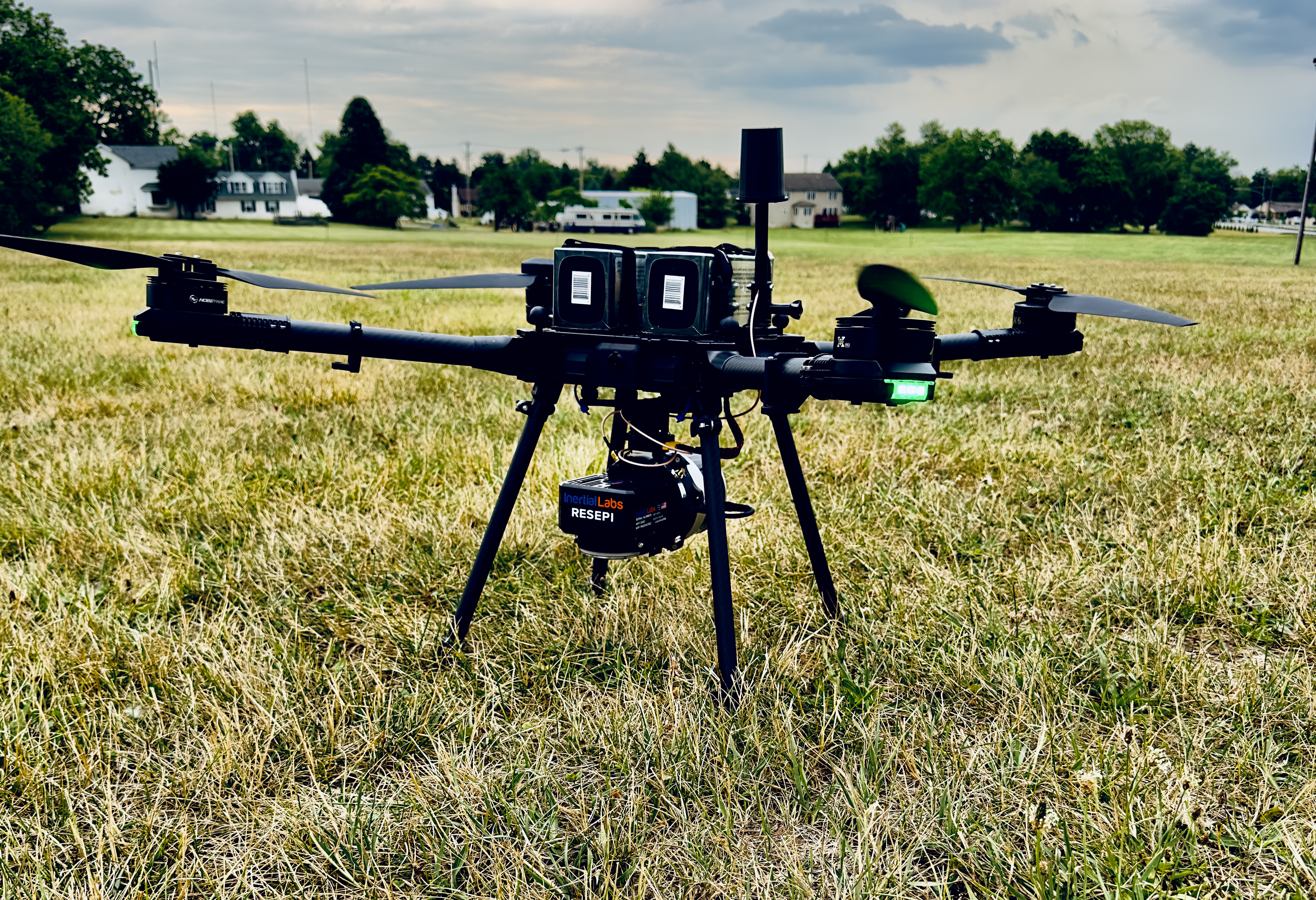
Aurora is the all-purpose Quadcopter designed to carry out complex tasks in various real-world conditions. Equipped with motors mounted around its core frame at equal intervals, the multirotor sUAS utilizes carbon fiber booms and a unique folding mechanism for both booms and propellers. The aviation-grade machined aluminum airframe houses an inner sealed compartment that contains avionics and supporting equipment. It also comes with aluminum bottom plates with data and power ports to cater to the operator's battery/payload integration needs. \
\
Aurora's integral Iso Mounting payload allows easy integration of payloads at the bottom of the airframe. Aurora can accommodate various battery capacities and configurations. The Auterion Skynode Flight-controlled version serves as the flight controller for Aurora, offering a range of features and capabilities. Custom ground control software manages commands and controls through a handheld controller, providing a direct connection to Aurora and real-time telemetry data for the safe direct-link operation of the sUAS. \
\
Each CamFlite sUAS is handcrafted with care in our New Jersey facility, with each subsystem undergoing rigorous testing before installation. Before delivery, we repeatedly test-fly each CamFlite sUAS to ensure it meets or exceeds published performance standards and is airworthy.
# Getting Started
## 1. Unboxing the Aurora
* [ ] Open the box and see the upper tray with the gear legs, transmitter, and controller.
* [ ] Remove the controller from the case, peel off the sticker from the controller screen, and press the power button. Once powered on, the AMC app opens.
* [ ] Install the gear legs, locking them before pulling out the Aurora.
* [ ] Pull out the Aurora and place it on a flat surface
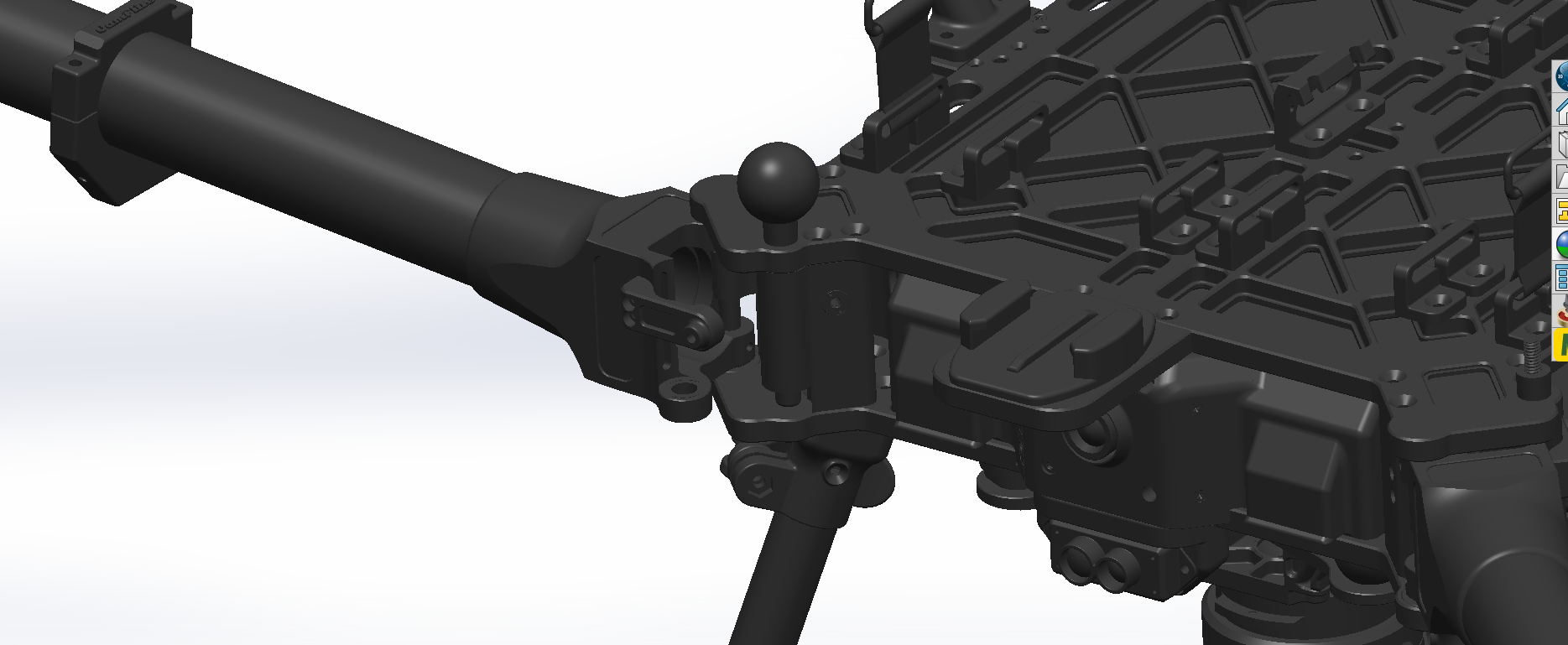
* [ ] To unlock the mechanism, pull the knob and swing the arms in place, **making sure the pin slides into the lower bushing as you twist the knob**. The knob might be tight at first, but it will loosen over time.
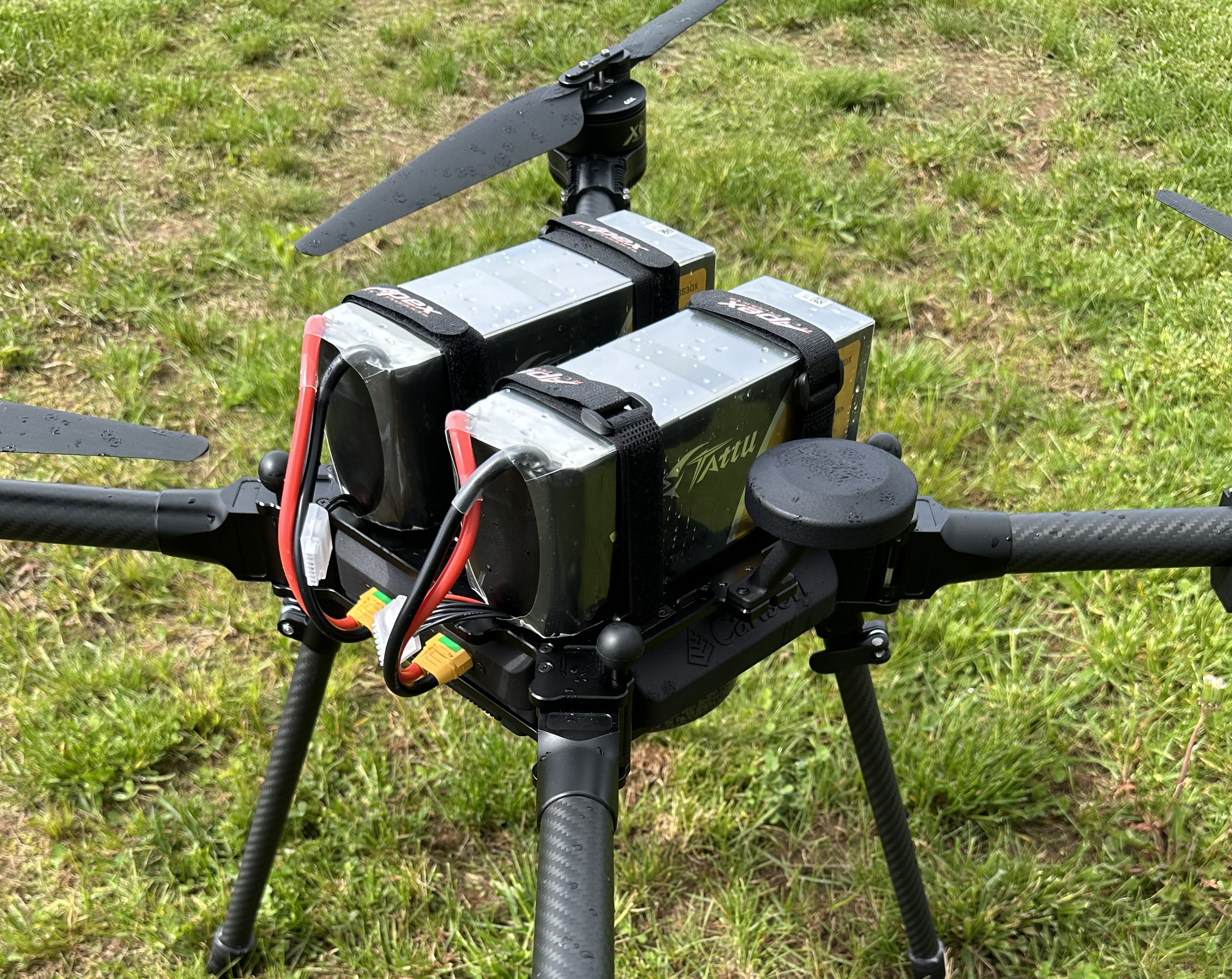
* [ ] Place (2)- 6s Lipo batteries on the top of the Aurora and strap them in place; when ready, plug the battery into their two receptacles on the back of the aircraft.
* [ ] Make sure all RF antennaes are screwed on.
* [ ] Install RTK GPS Mast
{% hint style="danger" %}
It's crucial to push down the boom lock all the way to ensure the booms don't open during the flight, which could lead to a crash. So, make sure to double-check the lock before flying!
{% endhint %}
## 2. Connecting your Aurora to the Internet
Connecting the Aurora to the internet allows you to connect to the Auterion Suite, load maps, download software updates, and communicate with your drone.
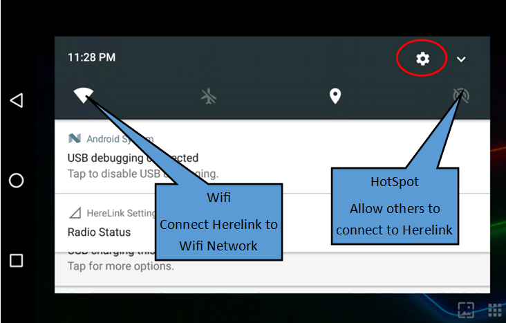
Connect your aircraft to a wifi network to ensure your drone is always connected to the Suite after a day of flying. To connect your Aurora to the wifi:
1. Open AMC Herelink or PC. If using a PC, connect to Aurora with a USB-C cable.
2. Power Aurora.
3. Tap the icon in the top-left of AMC. Navigate to Vehicle Setup > WiFi
4. Select Station mode, which allows Aurora to connect to another wifi network.
5. Enter the login credentials for your wifi access point.
6. Remote ID will need to have the WIFI disabled.
# Overview
Folded Up Booms
# Non-NDAA Controller
The Camflite MK15 controller in your Aurora is a sophisticated device developed to provide advanced control features. It has been specifically designed to work with your Aurora and comes with special software enabling you to operate it to its full potential. The software allows you to access a range of unavailable features with other controllers, giving you more control over your Aurora's functions. With the Camflite MK15 controller, you can adjust the settings of your Aurora according to your preferences and optimize its performance.
## Controller Features
## Battery
The MK15 transmitter comes with a built-in rechargeable battery of 10200mAh and a 20W PD fast charger. Please read the precautions carefully before using or charging the battery. Make sure to turn off the MK15 transmitter before charging, as it does not allow charging while it's in use.
Stop charging immediately if you notice that the charger is damaged, broken, or overheated. Similarly, if you smell something odd, see smoke, or leak, stop charging and send the transmitter back to your dealer for after-sales service. **Moreover, avoid charging the transmitter when the temperature is high or when the battery temperature is over 60℃.**
{% hint style="danger" %}
Please power off the MK15 transmitter before charging.
{% endhint %}
{% hint style="danger" %}
The transmitter must not be charged while in use. Stop charging immediately if the charger is damaged, broken or overheated.
{% endhint %}
{% hint style="warning" %}
If you notice any strange smells, smoke, or leaks while charging, please stop the charging immediately.
{% endhint %}
{% hint style="warning" %}
In case of any issues, please return the transmitter to your dealer for after-sales service..
{% endhint %}
{% hint style="warning" %}
It is important not to charge the transmitter when the temperature is high or when the battery temperature is over 60℃.
{% endhint %}
## Super Long Battery Life, 30W PD Fast Charging
The MK15 transmitter is equipped with high-capacity li-on batteries that provide excellent performance. These batteries have a stable and efficient discharging curve, ensuring the system's stability when operating at high speeds. The battery life of the MK15 transmitter is up to 12 hours. Additionally, the transmitter supports a max 30W PD fast charging, which can charge up to 95% of the battery level in just three hours.
## Memory Card (SD/TF)
The MK15 transmitter features a memory card slot at the bottom that can read and write to high-speed SD/TF cards.
## How to Use SIM Card on MK15
MK15 supports 4G network. Insert a SIM card to activate the function. Prior to insertion, check if your local cell network is supported.
Channel No.
Physical Channel Type
Default Mapping
Remark
1
Aileron
Joystick J1
2
Elevator (Mode 2)
Joystick J1
3
Throttle (Mode 2)
Joystick J1
4
Rudder
Joystick J1
5
Flight Mode
3-Stage Switch SA
6
3-Stage Switch SB
7
3-Stage Switch SC
8
Button A
9
Button B
10
Button C
PWM 1
11
Button D
PWM 2
12
Left Dial LD
PWM 3
13
Right Dial RD
PWM 4
14
PWM 5
15
Searchlight A
16
Searchlight B
## Specifications
Channels 13 physical, 16 communicational Datalink
Videolink Supported GCS (Standard RTSP video stream) QGroundControl MissionPlanner
Pro Transmitter (Ground Unit) Monitor 5.5-inch High Definition and High Brightness LCD Touchscreen System.
Android 9.0 2G RAM, 16G ROM
Dimension (Antenna Folded) 189 x 138 x 41 mm
Weight 850 g
Battery Capacity & Type 10200 mAh 7.4V 2S Li-on Fast Charging Protocol PD 30W Battery Life 15 hours
Interface & Ports Charging: Type-C Firmware Upgrade:
DATA (4-Pin) Mobile Network: SIM Card Slot External
Storage: TF Card Slot Tripod Connect: 1/4-inch Screw Hole
Video Output: Standard HDMI External RTK: DATA (4-Pin)
Data Transfer: USB-A
Waterproof Level IP53
Working Temperature -10℃ \~ 55℃ MK15
## Indicator Definition
The MK15 transmitter and receiver use three different colored status indicators that blink at different frequencies to indicate working or abnormal status.
## Power On/Off
To power the MK15 transmitter, you must perform a short and long press combo. To do this, press the power button once when the transmitter is off, and the battery level indicators will light up. Then, immediately press and hold the power button for about two seconds. The battery indicators will light up again, but this time one by one. This indicates that the transmitter is powered on.\
\
To power off the MK15 transmitter, you need to perform a long press. Press and hold the power button for about two seconds when the transmitter works. This will prompt the Android system to open a window with icons. Locate the power off icon and touch it to power off the MK15 transmitter.
{% hint style="warning" %}
Forced Shutdown: When the MK15 transmitter is working, press and hold the power button for about eight seconds, transmitter power will be forced to shut down.
{% endhint %}
## Charging
You can charge the MK15 transmitter only when it is powered off and using the original PD fast charger.
Steps:
1\. Connect the MK15 transmitter to the PD charger and plug it into the power supply.
2\. The charging indicator lights up red, and the transmitter starts charging.
3\. When the charging indicator turns green, charging is finished.
{% hint style="info" %}
A normal 5V charger adapter cannot charge the MK15 transmitter. Please use the SIYI original PD fast charger. MK15 transmitter cannot be charged when it is working. Please power off the transmitter before charging.
{% endhint %}
## How to Place MK15 Antennas
As shown in the photo below, the transmitter antenna should be placed vertically from the monitor, the head should point upward, and its flat side should always point to your aircraft or vehicle.
{% hint style="warning" %}
The two transmitter antennas should not be overlapped.
{% endhint %}
## FCC STATEMENT
This device complies with Part 15 of the FCC Rules. Operation is subject to the following two conditions:
(1)This device may not cause harmful interference, and
(2)This device must accept any interference received, including interference that may cause undesired operation.
NOTE: This equipment has been tested and found to comply with the limits for a Class B digital device, according to Part 15 of the FCC Rules. These limits are designed to protect reasonably against harmful interference in a residential installation. This equipment generates uses and can radiate radio frequency energy and, if not installed and used following the instructions, may cause harmful interference to radio communications. However, there is no guarantee that interference will not occur in a particular installation. Suppose this equipment does cause harmful interference to radio or television reception, which can be determined by turning the equipment off and on. In that case, the user is encouraged to try to correct the interference by one or more of the following measures: MK15 User Manual V1.1 85 2021 SIYI Technology, All Rights Reserved Reorient, or relocate the receiving antenna. Increase the separation between the equipment and the receiver. Connect the equipment to an outlet on a circuit different from that to which the receiver is connected. Consult the dealer or an experienced radio/TV technician for help.
# NDAA Controller
**Features**
Atlas Controller is a compact, lightweight, IP-rated mobile industrial handheld ground control unit. It includes a powerful computer, broadband datalink, HD Video transmission, LTE connectivity, touchscreen, and much more.
**Processor and Memory**
| Parameter | Value |
| --------- | ------------------- |
| CPU | Octa Core, 2.7GHz |
| RAM | 4GB |
| ROM | 64GB |
| External | MicroSD (Up to 1TB) |
**Radio**
| Parameter | Value |
| ---------- | ----------------- |
| Technology | 2x2 MIMO |
| Frequency | 2402 - 2482 MHz |
| Power | up to 30 dBm / 1W |
| Bandwidth | 4 / 8 MHz |
| Encryption | AES-256 |
| Data rate | 25 Mbps |
**Environment**
| Parameter | Value |
| ------------------- | ----------- |
| Resistance | IP-68 |
| Ambient temperature | -40...+50°C |
**Screen**
| Parameter | Value |
| ---------- | ------------------- |
| Size | 8" |
| Resolution | 1920 x 1200 (WUXGA) |
**Size & Weight**
| Parameter | Value |
| ---------- | ------------- |
| Dimensions | 286x166x57 mm |
| Weight | 1140 g |
**Battery**
| Parameter | Value |
| ---------------- | ------------------------ |
| Type | Li-Ion, fully integrated |
| Capacity | 5050 mAh |
| Charge current | 4A |
| Charge interface | USB Type C |
### Power up ATLAS Controller
* Open the Pelican case and remove the ATLAS Controller
* Make sure that the antennas are mounted properly
**WARNING**
Do not power on the radio module without antennas. It may significantly reduce the quality of the radio or damage the radio module permanently.
* Press the Power button for a second until the unit starts to power up. The boot-up process usually takes 15 seconds.
* After ATLAS is loaded up, ensure the WiFi is disabled for Ethernet to work correctly.
* If you wish to use radio connectivity, please press the power button on the radio module:
* Make sure that radio module status LEDs are blinking / solid:
**Start the Application**
Once ATLAS Handheld is loaded you can start the ground control station app. Click on AMC app on the main screen or apps menu.
### Power Off
* Close the ground control station app by returning to the main screen or pressing the home button.
* Press the Power button on the radio module to turn off the radio:
* On the controller’s homepage, use the drop-down menu on the top right of the screen to select the “Power Off” button or press the VOLUME DOWN and POWER buttons for the power off menu.
### Charging
Plug in the USB Type C cable to the USB port as shown in the image below:
{% hint style="warning" %}
The controller should not be left in a hot vehicle or operated in direct sunlight. On hot days, keep the controller from getting hot, as this can prevent a stable connection to the drone.
{% endhint %}
{% hint style="info" %}
Keeping the controller charged at about 40% will ensure long-range use. Use an external battery supply to keep the controller charged during operation.
{% endhint %}
## TroubleshootingSome troubleshooting guidance which will help to resolve the questions quickly.
| Problem | Solution |
| ----------------------------------- | ---------------------------------------------------------------------------------------------------------------------------------------------------- |
| Unit doesn't turn on | Make sure that the unit is charged. Connect the charger and try to power up the unit again. |
| Drone telemetry is not connecting | Make sure that your radio module is turned on the modules are paired. |
| Air module is not paired with ATLAS | Press and hold ATLAS reset button for 6 seconds. Press and hold Air module reset button for 11 seconds. After 30 seconds the modules will be paired. |
| I can't download the maps | Internet connection is required to download the maps. Make sure that you have active WiFi or LTE connection on ATLAS. |
| Not charging | If the tablet is not turned off properly and is allowed to fully discharge, it can take several hours for the charger to regain a charge. |
| Connection Issues | Most connection issues are related to the battery state of charge; under the 40% range, it can be reduced. Closing AMC will cause he drone to RTL. |
# Herelink Blue NDAA Controller
**Features**
Herelink Blue is created in a partnership between NW Blue LLC (a USA-owned and operated company) and CubePilot PTY LTD (an Australian-owned and operated company). The Herelink Blue offers the same features and functions as the original Herelink Black; however, the Herelink Blue is assembled and supported in the United States of America by NW Blue LLC.
Herelink Blue is an integrated remote controller, ground station and wireless digital transmission system designed to be used with the Cube Autopilot, Ardupilot, or PX4. HereLink Blue allows RC control, HD video, and telemetry data to be transmitted up to 20km between the ground station and air unit. NW Blue has also partnered with Solex to include a custom version of the Solex TX application installed on the Herelink Blue. Both the Air Unit and the Ground Control Unit feature an integrated 8-core SOC for custom application development.
Herelink Blue v1.1 is based on the original platform and functions of Herelink Blue v1.0. The controller improved the display brightness up to 1000 nit. Moreover, an additional Ethernet interface is available on the Air Unit v1.1 to support more peripheral devices and accommodate a broader range of applications. A SD card slot is available on the Air Unit v1.1..
| SOC | 4 \*Cortex A53, 2.2GHz / 4 \* Cortex A53, 1.4GHz |
| ------------------------- | ------------------------------------------------ |
| GPU | 4 Core, Mali-T860 |
| SDR | A7 + DSP |
| Memory | Air unit LPDDR3 1GB \| Controller LPDDR3 2GB |
| **Transmission Distance** | FCC 20km \| CE / SRRC / MIC 12km |
| Video Delay | 10 ms |
| **Image resolution** | 720p\@30fps \| 1080p\@30/60fps |
| **Frequency Band** | 2.4GHz ISM |
| **Receive sensitivity** | -99dBm\@20MHz BW |
# RTK GPS Mast Installation
You can find the RTK GPS antenna inside a compartment provided in the case. Screwon the RTK GPS anntenna onto the il mount base at the UAS's front.
{% hint style="warning" %}
Make sure the thumb screw is backed out enough to allow the RTK GPS to slide in before tightening the thumb screw.
{% endhint %}
{% hint style="danger" %}
If no GPS satellites are visible in the GCS after installing the RTK antenna, do not fly. Check to ensure that there is no damage to the connection. If there is any damage, contact Camflite.
{% endhint %}
# Powering
To ensure top-notch performance, it is recommended to use lipos with a capacity ranging from 16ah to 25ah, with an X90 connector rated at 22.2V, as the Aurora UAS can accommodate different sizes of lipos. It requires two 6s lipos to power up the drone, and force is unnecessary when plugging in the battery.
**Apply the provided Rubber foam to the bottom of each battery. That and the sinch strap is all that is needed to keep the battery in place. This lightweight solution has proven to be a foolproof method of attaching the batteries to the airframe.**
{% hint style="info" %}
Aurora uses standard LiPo 22.2v batteries, not HV LiPos with 22.8v. However, you can use HV LiPos if you charge them as a standard LiPo.
{% endhint %}
{% hint style="warning" %}
It is important to ensure that the batteries do not slide around, so attaching a self-adhesive neoprene rubber to the bottom of each battery is recommended. It is not necessary to tighten the battery straps excessively.
{% endhint %}
{% hint style="warning" %}
The connection of batteries results in full power for both the drone and the payload.
{% endhint %}
{% hint style="danger" %}
Please ensure that you wait at least 30 seconds before repowering after removing the power. Some capacitors need to discharge fully.
{% endhint %}
## Battery Charge Status
Battery Voltage Gauge
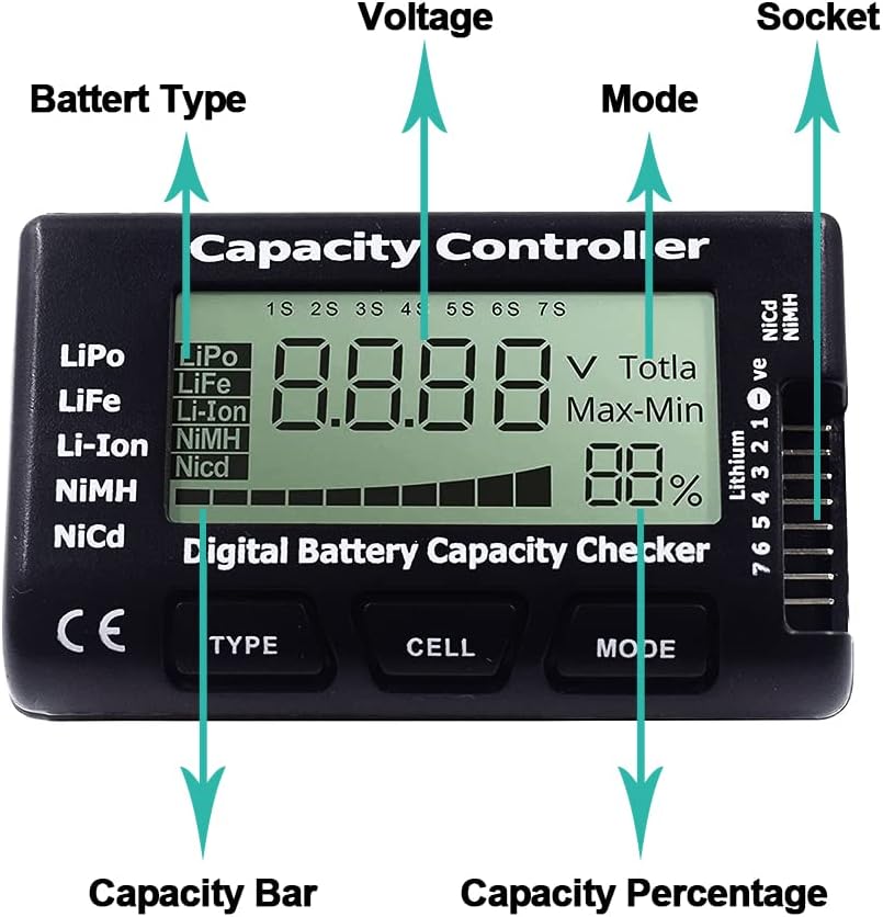
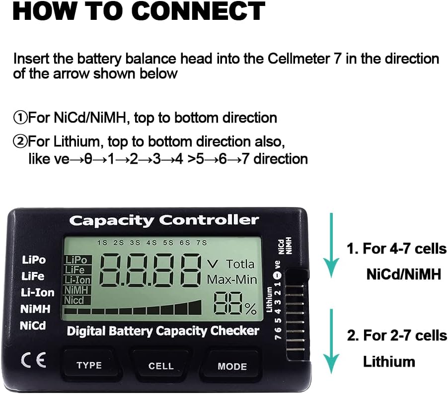
Connect the Battery Balance cable to the Battery Voltage indicator to check the battery voltage. Ensure the red wire is closest to the bottom of the voltage indicator when plugging the balance cable.
The balance plug's plastic guides should face the pilot while plugging it in.
A fully charged battery will show a 25 to 25.29-volt voltage reading.
To check battery status or remaining flight time, the pilot must understand how to gauge the remaining flight time.
{% hint style="info" %}
The battery voltage will fluctuate between 50 and 42 volts.
{% endhint %}
{% hint style="info" %}
Full Battery = 50 volts b. Empty Battery = 42 volts
{% endhint %}
Drone batteries are usually made of lithium polymers, and their depletion is exponential. These batteries work best when their capacity is between 100% and 30%. However, if the battery goes below a certain voltage level or percentage, it can lose power quickly, resulting in a crash. To avoid this, pilots must keep a close eye on the battery voltage throughout the flight to know how much flight time they have left.
# Motor Booms
The Aurora boasts a unique boom mount and locking mechanism. To secure or release the boom, one can effortlessly tug on the round ball, causing a spring-loaded pin to activate the boom's locking mount. After undergoing hundreds of hours of rigorous testing, no malfunctions have been reported during flight.
{% hint style="warning" %}
To prevent any harm or damage to the locking pin, it is crucial to make sure that the unlocked boom does not swing and hit the pin while it is in the down position.
{% endhint %}
{% hint style="info" %}
When new, the locking pin may feel stiff. It is crucial to ensure that the pin is fully engaged and bottomed out. This can be achieved by pushing and rotating clockwise.
{% endhint %}
## Propellors
Ensure that the propellers are not loose; the bolt attachment screws should be securely tightened to allow the propellers to slide but not flop. Regular inspection must be performed to check for any damage to any part of the propellers.
# Landing Gear
Firgure 6
The Aurora has four mounting points available for alternative landing gear systems. The lower plate is equipped with mounting locations for post-style landing gear with four points of attachment at the four corners, as shown in Figure 6. The process of installing the landing gear is straightforward: begin by opening the cam lock, then slide the gear into their respective holder and turn them 1/4 to locate them. Finally, tighten the screw to lock them in place.
# Flying
{% content-ref url="/pages/H0q3mPOmY4p2ZtZvNbyB" %}
[Flight Modes](/camflite-aurora-intro/flying/flight-modes)
{% endcontent-ref %}
{% content-ref url="/pages/bTofqmJMFoNBCK59J41I" %}
[Flying Procedures](/camflite-aurora-intro/flying/flying-procedures)
{% endcontent-ref %}
{% content-ref url="/pages/7TB13603llL3L0ZSuDKH" %}
[Emergency/Advanced](/camflite-aurora-intro/flying/emergency-advanced)
{% endcontent-ref %}
# Flying Procedures
## Aurora Check List
Below is a PDF you should print and keep to check before every flight.
{% file src="/files/3Kyq6DxvWISQQEm0bHrM" %}
## Issues Preventing Arming
You may occasionally encounter issues that will prevent Aurora from arming; please follow the next steps to resolve any issues-
## Compass Calibration
If AMC asks you to calibrate the compass and won't allow you to take off, follow the instructions to recalibrate sensors in an area without significant magnetic interference (far from large metal structures or magnetic/electric installations).
## Everything else
Check if the AMC message you're encountering is on our Error/Warning Spreadsheet, and follow the associated instructions. If you're still experiencing the issue, don't hesitate to contact for further troubleshooting.
## Arming and Disarming
Aurora's propulsion system has two fundamental states: Disarmed and Armed.
| State | Definition | Indication |
| -------- | ------------------------------------------- | ---------- |
| Disarmed | Safe mode, no spinning propellers | None |
| Armed | Aircraft will spin propellers, ready to fly | None |
Aurora can be armed with or without GPS.
{% hint style="info" %}
Pro Tip: Wait for GPS lock even if you don't plan to use Position Mode because Return Mode relies on GPS.
{% endhint %}
{% hint style="danger" %}
Before arming, ensure people and other obstacles are clear of the propellers. Be prepared for Aurora to take off.
{% endhint %}
The manual transitioning between armed and disarmed states is via the pilot handset throttle stick. (The pilot's handset default configuration is [Mode 2](https://docs.px4.io/master/en/getting_started/rc_transmitter_receiver.html#types-of-remote-controls).)
| State | Input |
| --------------- | ------------------------------------------------------------------------------------- |
| Arming (Mode 2) | Hold the throttle stick down and right for 2 seconds. |
| Disarming | When the aircraft has landed, continue holding the throttle stick down for 2 seconds. |
{% hint style="info" %}
It is not possible to disarm via the normal method while in flight.
To disarm during flight, perform an Emergency Stop.
{% endhint %}
{% hint style="info" %}
If Aurora does not arm, check Auterion Mission Control (AMC) for errors or warnings.
{% endhint %}
{% hint style="info" %}
Only use the throttle stick to Arm & Disarm. Aurora will not respond to two-stick input (i.e. DJI arming gesture). However, you can use the takeoff icon to arm and take of your Aurora automatically.
{% endhint %}
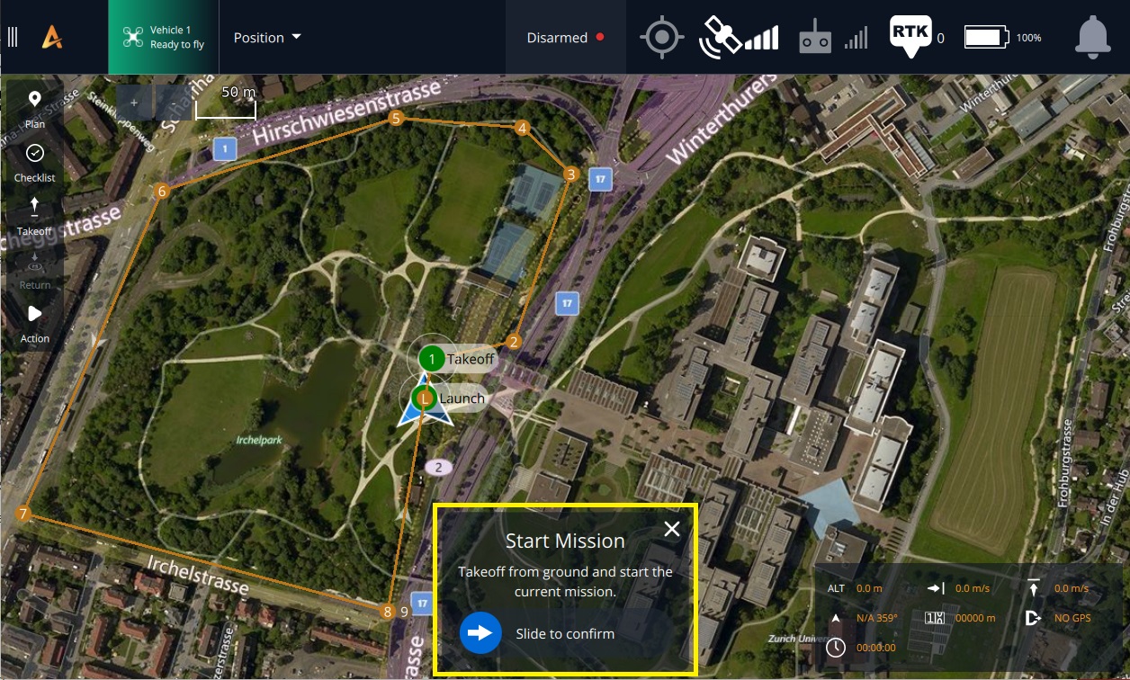
Missions may Arm and Disarm the aircraft automatically. For example, if a mission is started while the aircraft is disarmed on the ground, the aircraft will arm and take off.
### Automatic Disarm Methods
Under these conditions, Aurora will automatically disarm.
| Method | Aurora behavior |
| --------------------------------------- | ------------------------------------------------------------------------------------------------------------------------------------------------------ |
| Gon the round timeout before taking off | If Aurora sits on the ground at idle throttle for 10 seconds, it will automatically disarm. |
| Land mode | If Aurora is in Land Mode and detects a landing, it will disarm after 1 seconds. For example, this applies if the last command in a mission is "Land." |
### Automatic Disarm Methods
Under these conditions, Aurora will automatically disarm.
| Method | Aurora behavior |
| -------------------------------- | ----------------------------------------------------------------------------------------------------------------------------------------------------- |
| Ground timeout before taking off | If Aurora sits on the ground at idle throttle for 10 seconds, it will automatically disarm. |
| Land mode | If Aurora is in Land Mode and detects a landing, it will disarm after 1 second. For example, this applies if the last command in a mission is "Land". |
## Taking off
Position Mode is best for taking off in most cases, as it offers the most stabilization. However, taking off in Altitude, Manual, and Mission modes is certainly possible.
For 5 seconds after takeoff, the maximum pitch and roll angles are reduced to 12 degrees.
After takeoff, promptly climb out of the ground effect (i.e., to 3 feet / 12 meters of altitude) to avoid snagging landing gear on the ground.
{% tabs %}
{% tab title="Position and Altatude " %}
Once you have armed the aircraft, ensure that the throttle stick is returned to its central position. At this point, the propellers will be spinning. To initiate takeoff, simply raise the throttle stick. As a result, the aircraft will lift off the ground.
{% endtab %}
{% tab title="Manual Mode" %}
To prepare for takeoff, first arm the device. Then, hold the throttle stick straight down while avoiding any Yaw input. When ready, slowly raise the throttle stick. The propellers will start to accelerate as soon as the throttle stick moves. Once the throttle reaches the mid-point, there will be sufficient thrust to take off. Keep raising the throttle to achieve a smooth and brisk takeoff.
{% endtab %}
{% endtabs %}
## Landing
Position Mode is best for landing in most cases, as it offers the most stabilization. However, it is also possible to land in Altitude and Manual modes. The aircraft behaves a little differently in each mode.
{% hint style="danger" %}
Do not hand-catch Aurora. The aircraft is designed to be landed on hard flat surfaces away from people. Hand-catching can result in serious injury or death.
{% endhint %}
In Position and Altitude Modes, at altitudes below 6 feet, the maximum vertical speed is reduced to 0.7 m/s (from the normal value of 2 m/s).
Aurora will disarm automatically after the autopilot detects a landing. Landing detection brings input from several sensors to determine when it is safe to disarm.
{% hint style="warning" %}
If the landing is undetected (i.e., the props do not stop after touchdown), perform the Emergency Procedure for Landing Detector Failure.
{% endhint %}
{% tabs %}
{% tab title="Landing in Postion" %}
In order to successfully land your aircraft, you should first raise it to a height of at least 2 meters. Then, gradually decrease throttle input by pulling the throttle stick directly downward without making any pitch, roll, or yaw adjustments. The landing sensor on Aurora will manage the descent speed automatically. Once the aircraft reaches the ground, keep the throttle stick down until Auroa disarms and the propellers stop completely.\
\
It's important to keep in mind that if you're operating at altitudes below 2 meters, the maximum pitch and roll angle is limited to 12 degrees. This limitation is in place to prevent any sudden maneuvers that could cause the aircraft to tip over.
{% endtab %}
{% tab title="Landing in Altitude " %}
When switching to Altitude Mode during landing, it's important to remember that the pilot is responsible for controlling the lateral velocity of the aircraft. Although the autopilot regulates the descent rate by managing the throttle, the pilot must actively monitor and control the lateral speed.\
To initiate the landing process, hover the aircraft at a height of 2 meters above the intended landing area using minimal pitch and roll commands to reduce lateral speed and pitch/roll angles. Then, push the throttle stick downwards to begin the descent.\
After touchdown, keep the throttle stick in the downward position until the Aurora disarms and the propellers come to a complete stop. This will ensure a safe and controlled landing.\
It's important to note that when operating at altitudes below 2 meters, there are limitations on the allowable pitch/roll angles. These limits are reduced to 12 degrees to minimize the risk of sudden movements that could cause the aircraft to tip over.
{% endtab %}
{% tab title="landing in manual" %}
When switching to Manual Mode for landing, the pilot takes on more responsibility for controlling the aircraft's vertical and lateral velocity. To begin the landing process, hover the aircraft above the desired landing spot at a height of at least 2 meters. Use gentle pitch and roll commands to maintain a slow lateral speed and minimize pitch/roll angles.
Gradually reduce the throttle to allow the aircraft to descend smoothly. As the aircraft approaches the ground and enters the ground effect, the pilot may need to lower the throttle even further to maintain a controlled descent.
Once the aircraft touches down, quickly reduce the throttle to zero to prevent bouncing or dragging of the landing gear. It's important to keep the throttle stick down until the aircraft disarms and the propellers completely stop spinning, ensuring a safe landing.
{% endtab %}
{% endtabs %}
## Battery Changes / Hotswaps
{% hint style="danger" %}
The Aurora aircraft has a failsafe feature that automatically directs it back to the launch point when the battery level is low. Unfortunately, this mechanism cannot detect obstructions or potential problems that might hinder a safe landing before the battery is entirely depleted. If the failsafe is triggered while the aircraft is far from the launch point, there may not be enough battery power to complete the return journey. Hence, it falls to the pilot to assess the situation and decide when to replace the battery to ensure a secure landing.
{% endhint %}
# Flight Modes
Aurora provides the pilot with different levels of assistance through its multiple flight modes. You can switch between these modes using the pilot's handset or the AMC app on Herelink or PC. It's recommended to refer to the documentation for the equipment you use to familiarize yourself with the buttons or switches involved in the process.
Aurora offers several flight modes with varying levels of assistance to the pilot. Flight mode can be changed via the pilot's handset and the AMC app on Herelink or PC. See the documentation for the equipment you use to familiarize yourself with the buttons/switches involved.
{% hint style="info" %}
Manual Mode may be necessary to react to emergencies. Pilots should be proficient in Manual Mode. Position, Altitude, and Return Mode are assistive only and are not a replacement for pilot skill and preparedness.
{% endhint %}
{% hint style="danger" %}
Always neutralize the control input sticks on the pilot handset when switching between control modes to prevent unexpected aircraft movement.
{% endhint %}
{% hint style="info" %}
The Aurora does not ship with Manual Mode enabled; if you require that, contact us for how to add that option.
{% endhint %}
### Pilot-controlled Modes
{% tabs %}
{% tab title="Position" %}
When the sticks are in the middle, the aircraft will hold position over a spot on the ground while maintaining altitude and compensating for disturbances in Position Mode. With Position Mode, the drone's speed in relation to the ground is controlled via the pitch/roll stick. The pitch/roll stick's height will determine how quickly.
Aurora moves forward. Aurora will fly backward if the pitch/roll stick is dragged downward. Similarly, moving the pitch/roll stick to the left or right will cause the drone to go in a left or right direction. The throttle stick controls vertical speed. The quicker Aurora climbs, the higher the throttle stick is moved. On the other hand, Aurora will fall more quickly the lower the throttle stick position is set. The yaw is managed by moving the throttle stick in opposite directions.
{% endtab %}
{% tab title="Attitude" %}
The pitch/roll stick is used for lateral movement to control the Aurora drone, while the throttle stick controls the vertical speed and yaw. The drone relies on the barometer and GPS to maintain its vertical position in Altitude mode. However, the autopilot does not control the lateral speed, meaning the drone may drift with the wind without pilot input and will not immediately stop after lateral movement. Therefore, the pilot should always be attentive and adjust to keep the drone in a single position above the ground.
{% endtab %}
{% tab title="Manual" %}
**Manual mode is not set up by default but can be configured by the user.**
When operating in manual mode, the aircraft will maintain level flight and drift with the wind if the pitch and roll sticks are in the middle position. To maintain altitude, the throttle will require constant adjustments. The pitch and roll sticks determine the aircraft's angle. By raising the pitch stick, the aircraft will lean forward, and by lowering it, the aircraft will tilt rearward. The same applies to rolling left and right. The autopilot does not control lateral speed; direct motor speed control is used through the throttle stick. The Yaw rate is adjusted by moving the throttle stick left or right, with stick deflection affecting yaw rotation speed proportionally. By default, the thrust created by Aurora when the throttle stick is in the middle is set to 34%. This setting allows Aurora to hover, and a payload of up to 1500 grams can hover at around 40%. These are the settings for Manual Mode.
{% endtab %}
{% endtabs %}
{% hint style="info" %}
To activate Position Mode, a robust GPS signal is required. Aurora cannot enter this mode if a weak signal is detected. If the signal weakens, for instance, when close to buildings or under thick tree coverage, the aircraft will automatically transition to Altitude mode.
{% endhint %}
{% hint style="danger" %}
When flying in areas with weak or disrupted GPS signals, like near buildings or under dense tree cover, it's best to avoid using Position Mode. This is because the automatic transition to Altitude Mode may cause unexpected changes in flight behavior, which could be dangerous.
{% endhint %}
### Autonomous Modes
{% tabs %}
{% tab title="Return Mode" %}
To activate Return Mode, the pilot can direct Aurora to ascend to a specific Return Altitude, fly straight back to the Home Point, and land safely. It's important to note that GPS capability is necessary for Return Mode to function correctly. The pilot can set the Return Altitude in AMC > Vehicle Setup > Safety. However, if Aurora is already at or above the Return Altitude when Return Mode is activated, it will remain at its current altitude rather than descending. The GPS coordinates at which Aurora is armed determine the Home Point, which is reset every time Aurora is armed. Additionally, certain Failsafes may trigger Return Mode automatically. For further information on Failsafes, kindly refer to the manual.
{% hint style="danger" %}
A helpful tip to ensure safe flying is to consider the aircraft's path in case Return Mode is triggered. It's important to adjust settings accordingly to prevent any mishaps. For instance, turning on Return Mode while flying under an obstacle lower than the Return Altitude could result in a collision when the aircraft tries to ascend to that altitude. Depending on the situation, it may not be feasible to set a lower Return Altitude or use Return Mode at all.
{% endhint %}
{% hint style="info" %}
If you want to switch from Return to Position Mode, you can do so by moving the sticks. However, if the low battery failsafe has activated Return Mode, you must press a different flight mode button to exit Return Mode.
{% endhint %}
{% endtab %}
{% tab title="Takeoff Mode" %}
To initiate Takeoff Mode, simply use the button located in the Fly view section of the AMC (Aurora Mission Control) app. Once activated, the aircraft will ascend to the designated Takeoff Altitude before entering Hold Mode (also referred to as loiter or hover). You can adjust the Takeoff Altitude using the provided slider and confirm your selection by holding or sliding the button. It's important to note that Takeoff Mode can also be initiated during a mission and set as the first command.
{% hint style="info" %}
Takeoff Mode requires GPS lock
{% endhint %}
{% hint style="info" %}
Moving the sticks while in Hold Mode (i.e. after the aircraft has finished climbing) will cause a change to Position Mode. This makes it easy to take control without pressing the Position Mode button.
{% endhint %}
{% endtab %}
{% tab title="Landing Mode" %}
Aurora has a Landing Mode feature that allows it to accurately descend and land at the exact point where Land Mode was activated. Once the landing is complete, Aurora will disarm itself. To activate Landing Mode, simply locate the button on the AMC app Fly screen and hold it down to confirm the switch. Typically, Landing Mode is used as the last command during a mission. However, it can also be triggered automatically as a failsafe measure if there are issues such as low battery level or signal loss.
{% hint style="info" %}
When Land Mode is manually engaged, GPS is required. However, if Land Mode is triggered by a failsafe and GPS is unavailable, the autopilot will act like Altitude Mode, and the aircraft may drift horizontally while descending.
{% endhint %}
{% hint style="info" %}
If you move the sticks, the Position Mode will be affected, unless the Landing Mode is activated by a Failsafe, such as a critically low battery. For more information, please refer to the Safety and Failsafes section.\
When the Return and Landing Mode is triggered by a low battery failsafe, stick movement won't override it. However, it can still be overridden by pressing a flight mode button, like the Position button.
{% endhint %}
{% endtab %}
{% tab title="Mission" %}
Aurora can execute a pre-determined autonomous mission using Mission Mode by accessing the flight controller through AMC. For a comprehensive understanding of Mission Mode and its functionalities, kindly refer to the relevant sections in the AMC documentation.
* [Planning a mission](https://docs.auterion.com/operators/flight-operations/fly)
* [Flying a mission](https://docs.auterion.com/operators/flight-operations/fly/flying-a-mission)
{% hint style="danger" %}
Starting a mission can cause the aircraft to arm itself and take off without any further pilot input. Before starting a mission, ensure the aircraft is clear of obstacles in the propeller arc and flight path.
{% endhint %}
If a mission is interrupted (for example, by the pilot switching to Position mode), the Fly view will prompt to resume the mission. If a prompt is not shown, open the [Action Menu](https://docs.auterion.com/operators/flight-operations/fly/flying-a-mission) and select "Resume Mission."
{% hint style="info" %}
Moving the sticks will cause a change to Position Mode. This makes it easy for the pilot to take control if needed.
{% endhint %}
{% hint style="info" %}
Aurora requires a GPS lock to initiate a mission to set a valid home position before takeoff. If the aircraft takes off without it, the mission mode becomes unavailable. The pilot must land and rearm with a GPS lock to activate it..
{% endhint %}
{% endtab %}
{% endtabs %}
### Multicopter Position Slow mode
#### What is it?
Position Slow is a new flight mode that acts the same as the traditional Position mode, with the difference that maximum speeds can be significantly reduced.
When configured, this flight mode allows operators to dial in the maximum horizontal and vertical speeds that the vehicle can achieve with RC Knobs.
In case the GCS does not have auxiliary knobs, users can still benefit from this flight mode. When engaged, the maximum horizontal speed of the vehicle will be constrained to 3m/s, which will make it compliant with the "Low-Speed Mode" required by EASA to fly closer to people.
In addition, this flight mode also supports as input a MAVLink message [VELOCITY\_LIMITS](https://github.com/Auterion/mavlink/blob/9d025e7b1f8cb98a78bead86e5b789c9c7c16a66/message_definitions/v1.0/development.xml#L430-L437). This message can be used to develop third-party apps on Skynode that will define dynamic velocity limits based on external factors, for example, reducing the velocities based on the camera's optical settings.
#### How to use it?
Position Slow is available for selection by default in the Flight Mode Selector available in the latest AMC provided with this release.
Alternatively, it can also be mapped to the flight modes controlled directly by the GCS by leveraging the `COM_FLTMODE*` parameters.
Other settings, such as lower speed limits and default speed, can be defined with the parameters that start with `POSSLOW_*` parameters.
# Emergency/Advanced
## General Guidance
Aviation safety should always prioritize human safety above everything else. While an aircraft can be replaced, human lives are invaluable. In any emergency, it is vital to prioritize the safety of oneself and others over preserving the equipment or the aircraft. Emergencies are unpredictable and may not fit into pre-defined categories, but having a comprehensive understanding of aircraft systems, piloting proficiency, and sound judgment can significantly increase the chances of achieving the best possible outcome. Proper maintenance, using checklists for normal procedures, and carefully planning pre-flight can substantially reduce the chances of emergencies. The pilot's diligence is crucial in ensuring a safe flight before takeoff and during operation. In most emergencies, three basic actions can be taken.
* Maintain aircraft control
* Analyze the situation
* Take appropriate action.
{% hint style="warning" %}
If the drone behaves abnormally, do not continue to fly land immediately. Contact Camflite for further instructions. Any anomaly should not be ignored; it is better to be safe than sorry.
{% endhint %}
During an emergency, the pilot needs to keep visual contact with the aircraft to prevent small issues from becoming bigger problems. Once the situation is under control, it is necessary to identify the cause of the emergency and take the appropriate action. In most cases, this involves landing the aircraft as soon as possible, as it can always be replaced.
### Return Mode
During emergencies, it's important to not solely rely on Return Mode as it may not be effective due to potential aircraft performance issues or loss of GPS signal. It's advisable to have alternative contingency plans and strategies to ensure a safe outcome in an emergency.
{% hint style="danger" %} When landing or maintaining aircraft control becomes impossible, the Emergency Stop should only be considered a last resort.
{% endhint %}
When considering the need to perform an emergency stop on an aircraft, it is essential to remember that doing so while the aircraft is in the air would result in a catastrophic crash. Therefore, if an emergency stop is necessary, it must be executed in a location as far from people as possible to minimize the risk of harm or damage to others. Exploring all other options and prioritizing safety before resorting to an emergency stop is crucial.
## Error and Warning Indication
The aircraft uses Auterion Mission Control (AMC) status indicators on the pilot handset or PC to communicate the presence of errors and warnings. Most messages are accompanied by an audible message, such as "Return Flight Mode". Moreover, the Aurora boom LEDs will start flashing when the battery level is low.
Status messages, including errors and warnings, are stored in Flight Logs. After an emergency, review the log to determine the source of the problem.
If the meaning of an error or warning is unclear, don't hesitate to contact Camflite Support. Share as many details as possible, including the flight log.
## Emergency Procedure Checklists
The Aurora checklists provide concise instructions to mitigate risks resulting from hardware, connection, or pilot errors. Further details are provided below.
### Loss of Orientation
If the aircraft's orientation is lost, neutralizing the inputs and activating the position mode are recommended. The next step is to work on identifying the front of the aircraft. We suggest using a "guess and check" method consisting of small roll-right inputs while yawing the aircraft 90 degrees at a time. Using a roll input rather than pitch is better because lateral motion is easier to see at a distance than fore/aft motion.\
\
If it is impossible to identify the orientation and it is safe to activate the Return Mode, we recommend doing so. In Return Mode, by default, the aircraft will yaw to put the front towards the direction of flight after climbing.
Resume flying or land as necessary.
### Unexpected Aircraft Behavior
If the Aurora aircraft behaves erratically, perform the following steps: neutralize inputs, activate Position Mode, and observe the aircraft. If it continues to fly in an uncommanded manner in Position or Altitude Mode, switch to Manual Mode.
In some cases, unexpected behavior may occur due to degraded GPS signals or erroneous sensor readings. Return Mode may not behave reliably in such cases. However, Manual Mode does not rely on these sensors.
Land as soon as possible.
{% hint style="warning" %}
If the drone does anything out of the norm, contact Camflite for help.
{% endhint %}
### Landing Detector Failure
If the aircraft bounces back into the air or remains on the ground with the propellers still spinning after touching down, it's possible that the autopilot did not register the landing. In this case, you should climb up and try landing again with a greater downward speed.
{% hint style="info" %}
Landing the aircraft firmly will give the accelerometers and gyroscopes a sufficient contrast between flight and landing.
{% endhint %}
If an attempted landing in Position and Altitude mode is unsuccessful, land in Manual Mode.
If an attempted landing in Manual Mode is unsuccessful, perform an Emergency Stop with the aircraft on the ground or as close as possible.
### Loss of GPS
If the GPS connection is lost during flight, the aircraft will switch to (Altitude Mode), and GPS-reliant flight modes such as Position, Return, and Mission will not be available.
{% hint style="info" %}
It is the pilot's responsibility to be proficient with altitude and manual mode and to have the aircraft configured safely in case of GPS loss.
{% endhint %}
Examples of behavior without GPS:
* If GPS is unavailable when arming the device, the Home Point will not be set, and Return Mode will be unavailable during the flight. Even if GPS becomes available later, Return Mode will not be available.
* If the pilot tries to enter Return Mode, an error will be displayed on the pilot's handset, and the aircraft will remain in its current mode (Altitude or Manual).
* If Land Mode is activated, for example, due to a failsafe, the aircraft will descend as if it were in Altitude mode. It will maintain a consistent attitude but drift with the wind. However, it's worth noting that the pilot cannot activate Land Mode because it requires GPS.
* If GPS is lost during a mission, the aircraft will display a warning and switch flight mode to either Altitude Mode or Manual Mode, depending on the degradation of the signal.
* Loss of GPS due to electronic connection issues can lead to total loss of control.
* If GPS provides altitude information, such as when using (RTK GPS), the Altitude Mode's ability to maintain altitude accurately may be affected if GPS is lost.
### RC Loss of Signal (LOS)
RC Loss of Signal (LOS) can occur if the pilot's handset signal degrades or stops or Aurora doesn't receive the signal due to distance or interference (e.g., obstacles or other radio signals).
A failsafe mechanism will be activated if the remote control signal is lost longer than the RC Timeout. The RC Timeout is set to 0.5 seconds, which may not allow enough time for the pilot to react before the failsafe mechanism is triggered. By default, the failsafe mechanism will activate the Return Mode.
If the signal is lost, check the power and orientation of the pilot's handset antenna, especially when Aurora is far from the pilot.
If the signal is recovered, the pilot can take control by moving the sticks or pressing a flight mode button.
{% hint style="info" %}
Please note that there are two types of signal losses in RC (remote control) systems: Loss of Signal (LOS) and Data Link Loss. LOS refers to the SBUS data stream containing the pilot's inputs, while Data Link Loss refers to the stream of MavLINK messages. Aurora routes both data streams through a single radio system. It is important to remember that during operation, the AMC (Aurora Mission Control) app must be in the foreground on the pilot handset. Otherwise, the Data Link will fail after 30 seconds and trigger a failsafe. So, if the AMC app is closed or running in the background, the Data Link will fail, and the failsafe will be triggered.
{% endhint %}
### Loss of Video Signal
Video signal loss can occur if the aircraft flies out of range or behind an object that blocks the signal. The best way to regain control of the aircraft is to maintain visual contact. This can be achieved by the pilot seeing the aircraft or using a visual observer.
Yawing the aircraft can improve signal reception if the aircraft body is blocking the line of sight between transmitter and receiver antennas.
If the video signal or visual contact is lost, activate Return Mode to bring the aircraft back within signal reception range.
{% hint style="danger" %}
As a pilot, it is your responsibility to be vigilant and avoid any potential collisions with other aircraft or obstacles. During flight, you must maintain a direct line of sight with Aurora and adhere to the see-and-avoid requirements mandated by local regulations. Additionally, you may use visual observers as needed to ensure the safety of your operations.
{% endhint %}
## Failsafes
AMC configures failsafe behavior and settings. The AMC documentation covers each failsafe and related setting in detail.
Some failsafes are discussed briefly below.
{% hint style="warning" %}
We highly recommend using the default settings and only modifying the Return Altitude unless you're an expert user who has extensively tested the impact of changes.
{% endhint %}
### Low Battery
Battery level is evaluated based on the State of Charge (SoC, e.g., 72%), not voltage (e.g., 23 Volts).
The aircraft safely lands when the battery level of the aircraft becomes low, and the autopilot system can take action. However, the system's default settings do not intervene until the battery level becomes very low. Furthermore, the low battery failsafes cannot determine the position or distance of the aircraft from its Home Point. Therefore, the pilots are responsible for monitoring the battery level and ensuring the aircraft safely lands on the ground.
| State | SoC (default) | Action (default) |
| --------- | ------------- | ---------------------- |
| Warning | 20% | Warning: Audio Message |
| Critical | 15% | Return Mode |
| Emergency | 6% | Land Mode |
# Remote ID
"*As of December 16th, 2022, no person may produce an unmanned aircraft for operation in the airspace of the United States unless the unmanned aircraft is designed and produced to meet the minimum performance requirements for standard remote identification unmanned aircraft in accordance with Part 89.*
*After September 16, 2023, no person may operate an unmanned aircraft within the airspace of the United States unless the operation meets the requirements of* [*§ 89.110*](https://www.ecfr.gov/current/title-14/section-89.110) *or* [*§ 89.115*](https://www.ecfr.gov/current/title-14/section-89.115)*."* \
\
*-*[*14 CFR Part 89*](https://www.ecfr.gov/current/title-14/chapter-I/subchapter-F/part-89)
{% hint style="success" %}
Aurora [UAS Declaration of Compliance](https://uasdoc.faa.gov/listDocs/RID000000241)
{% endhint %}
At Camflite, we prioritize adherence to the laws and regulations that apply to our customers' operations. To ensure compliance with the FAA's Remote ID mandate, all Aurora aircraft come equipped with enabled Remote ID, which cannot be disabled by end users.
# How Remote ID works
## Broadcast Method
The current Remote ID implementation in AuterionOS on Skynode is using the WiFi Beacon transmission method, where Remote ID information is embedded into [WiFi Beacon frames](https://en.wikipedia.org/wiki/Beacon_frame). Every device that scans for WiFi networks and is within range therefore has access to the drone's Remote ID information.
## Remote ID Data
AuterionOS streams the basic ID message, aircraft location and system message from the GCS in every WiFi Beacon frame. More specifically, the frames contain:
* GCS Information:
* Latitude and Longitude of the GCS
* Geometric altitude of the GCS
* Vehicle information:
* Vehicle serial number or session ID
* Latitude and Longitude of the vehicle
* Geometric altitude of the vehicle
* Velocity of the vehicle expressed as
* Track direction
* Horizontal and vertical speed
* Coordinated Universal Time (UTC) timestamp of this data
* Operational or emergency status of the vehicle
# Remote ID indicators in AMC
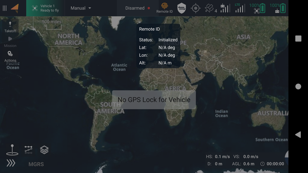
### Orange icon: Initialization
The orange icon indicates that the Remote ID system is in the initialization state. The Remote ID application on Skynode has not yet received any messages from either APX4 and AMC. If this state persists, there are two likely reasons:
1. The GCS has no position fix, either because the sensor is missing or disabled, or because the signal quality is not good enough.
2. APX4 is not communicating with the Remote ID application in AuterionOS. This should only happen during development when the APX4 version is not up to date.
The GCS position can be checked by tapping the Remote ID icon in AMC. If the Lat, Lon and Alt fields are populated, this means that the GCS is good to go and waiting for the drone to finish initialization. An example is shown in the screenshot below:
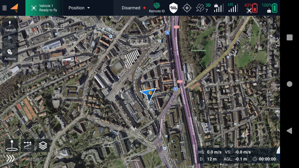
### Green Icon: Healthy
A green icon indicates that the Remote ID system is healthy and the drone is ready to fly.
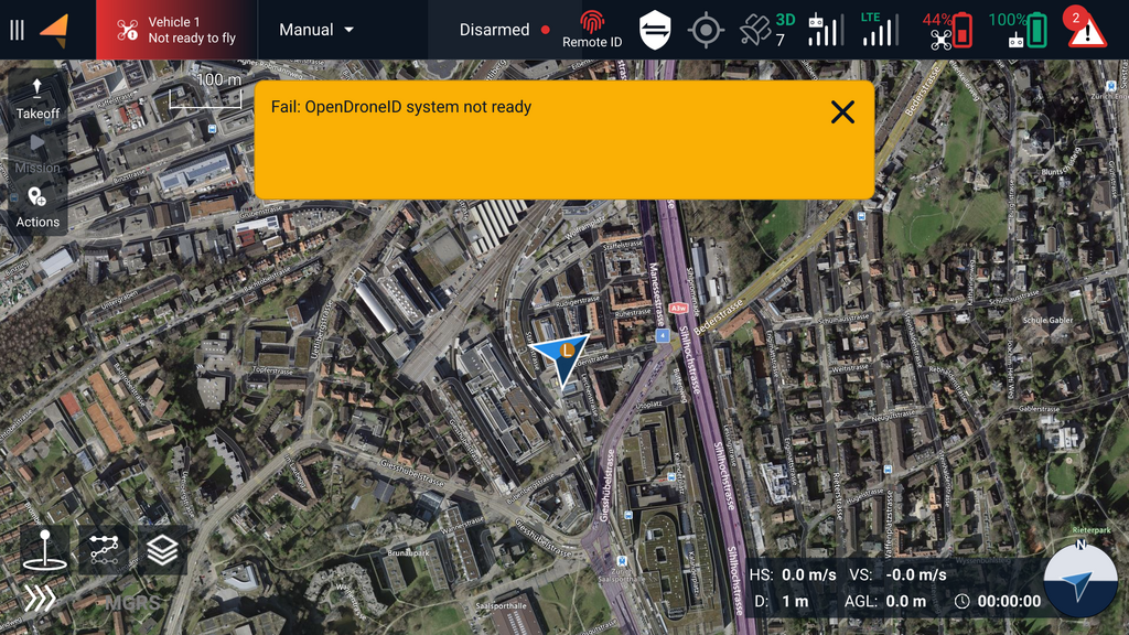
### Red Icon: Failure
The failure state is entered if the Remote ID system was healthy at one point and then encountered an error during operation. One reason might be that Remote ID stopped receiving a heartbeat from either AMC or APX4
### Grey Icon: Not enabled or not supported
A grey Remote ID icon in AMC means that Remote ID has either not yet been enabled or the AuterionOS version installed on the vehicle does not have support for it.
# Frequently Asked Questions
## How does Skynode broadcast the Remote ID?
Skynode is currently using WiFi beacon frames to broadcast the Remote ID Data. More details can be found on the page How [Remote ID works](https://docs.auterion.com/operators/settings-and-maintenance/remote-id/how-remote-id-works).
## Can Skynode's WiFi still be used alongside Remote ID?
Currently, it is not possible to use regular WiFi while Remote ID is enabled since Auterion then cannot guarantee that the message interval is strictly lower than 1s at all times.
## Can Remote ID be disabled on Skynode?
Only developers and manufacturers can temporarily disable Remote ID.
##
*References Provided by Auterion*
# Serial Number
To comply with ANSI/CTA-2063-A and § 89.505, the vehicle serial number uses Camflite registered manufacturing code, followed by a single character denoting the serial number's length, and then the actual device serial number. The vehicle serial number will be displayed on a prominent label in English on Aurora's front left arm socket. The label will be permanently affixed to both the unmanned aircraft and its packaging, ensuring its legibility.
The serial numbers of the Aurora are as follows:
| Bit position | Content | Meaning |
| ------------ | ---------------------- | -------------------------- |
| 1-4 | 1785 | 4 character MFR code |
| 5 | C | 1 character length code |
| 6-12 | 00000000xxxx (example) | 12 character serial number |
An example of a full serial number for Aurora will look like 1871C000000007000. This is the entire serial number you must use when registering your drone via the [FAA Drone Zone](https://faadronezone-access.faa.gov/#/).
## Serial # Tag
To register with the FAA, you will need to use your serial number. As per § 89.525 regulations, Aurora will display a laser-engraved tag on the bottom of the aircraft with the label "ASTM-F3586-22-NOA-22-01". This label will indicate that the aircraft meets the requirements under this part. It will be in English, legible, prominent, and permanently affixed to both the unmanned aircraft and its packaging.
# Resgistering with the FAA
## Public DOC List
To ensure your Aurora drone (serial number) complies with Part 89 Remote ID regulations, you must have an FAA-accepted Declaration of Compliance (DOC) listed on the Public DOC List. This is in addition to meeting our Scope of Compliance. Without a listed [DOC](https://uasdoc.faa.gov/docs/RID000000241), you won't be able to register your drone with FAA Drone Zone.
> **UAS Declerastion of Compliance**
## FAA Drone Zone
Follow the instructions below to properly fill out your FAA registration for Aurora:
1. Login or Create an Account with the [FAA Drone Zone](https://faadronezone-access.faa.gov/#/login).
2. Launch Drone Owners and Pilots Dashboard
3. Navigate to your Part 107 Dashboard
4. Select Manage Device Inventory
5. Select Add Device
* DOES YOUR DRONE BROADCAST **FAA REMOTE ID** INFORMATION?\* - Select *Yes* **(required)**
* UAS TYPE\* - Select *Standard Remote ID* - **required**
* NICKNAME - Enter the nickname of your choice (example: Aurora xxxx)
* UAS MANUFACTURER\* - Enter CamFlite - **required**
* UAS MODEL\* - Enter Aurora - **required**
* REMOTE ID SERIAL NUMBER\* - Enter the entire serial number using the above format (example: 1871C00000000xxxx where xxxx would be the last four digits of the serial number assigned for your aircraft) - **required**
# Software
{% content-ref url="/pages/CpvJPkhZnoSNCLaOyFGn" %}
[Auterion Mission Control](/camflite-aurora-intro/software/auterion-mission-control)
{% endcontent-ref %}
# Auterion Mission Control
Auterion Mission Control (AMC) is a ground control station application for pilots. It can be used to fly aircraft, to plan missions, fly missions, and to configure the aircraft. It can run on Herelink and PC.
Auterion's complete documentation is here: [https://docs.auterion.com/operators/getting-started/readme.](https://docs.auterion.com/operators/getting-started/readme)
# Fly
## Camera View
This screen includes a live camera feed, telemetry, and camera/gimbal control. You can also launch uploaded missions or take off using the touch screen.
## Map View
This screen displays the nearby satellite map and the current mission if uploaded.
## Pre-Flight Checklist
There is an optional checklist that can help you ensure the safety of your flight. This checklist can be accessed by tapping the Vehicle box located on the top-left corner of your screen. You can manually verify each item before takeoff by tapping on the yellow boxes, which will turn green once verified. \
\
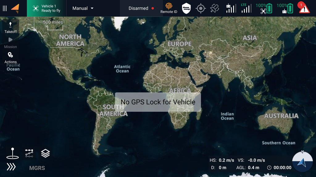
If there is a warning or error, it will be indicated by a red item on the checklist. Some items are crucial and will prevent takeoff, such as insufficient battery power, while others will allow for takeoff with some limited usage. For example, if there is no GPS signal, the aircraft will only be capable of taking off in Manual mode.
# Plan
*Plan View* is used to define vehicle plans that may include any (or all) of:
* [Missions](broken://pages/-Lt3qikfLbz2UjS0e4wu): Autonomous missions, including ground and building surveys.
* [GeoFences](broken://pages/-Lt3oxNSUh1IuFmWyMmY): Virtual fences that define areas where the vehicle can safely move.
* [Rally Points](broken://pages/-Lt3pi3I9PrKi1LgENIW): Alternative safe destinations when in [Return mode](broken://pages/-LtSV3pXHTYBJU_bANTn#return-mode).
### Front Overlap
Please note the following information without attributing it to an AI-powered assistant:\
\
Front overlap is the amount of overlap each sequential image has with the previous image. This means you will take pictures more frequently on each straightaway of your mission.\
\
The benefit of having a higher front overlap is that it will likely result in a more consistent map. This is because the stitching software will be able to connect the discreet images together more easily.\
\
However, there is a tradeoff in that you will take more pictures, many of which may be somewhat redundant. This will take up more storage and require more processing time.\
\
When changing the front overlap value, remember that your photo interval needs to exceed or equal to 2.0 seconds. This is because the USB drive cannot save large images any faster.\
\
Recommended value: 70%
### Side Overlap
#### Definition
The overlap amount between each image in a parallel leg of the mission. Higher values indicate closer proximity to neighboring swaths.
#### Benefit
Increasing the amount of side overlap improves stitching software consistency by introducing more landmarks.
#### Tradeoff
Increasing the side overlap during your mission can result in a longer flight duration, as more passes will be required over the same area. Unlike increasing the front overlap percentage, increasing the side overlap percentage will not affect the photo interval. However, it will increase the total number of pictures taken.
Recommended value: 70%
### Altitude vs. Ground Resolution
Please make sure to select one of the Survey options: Altitude or Grnd Res. These two options are directly proportional and can be selected based on your mission area and requirements. \
\
Grnd Res, which stands for Ground Resolution, is an approximation of the fidelity of each image in comparison to real-world measurements. For instance, a ground resolution of 1 cm/px means that each pixel in the resulting map will be approximately 1 centimeter long.\
\
This measurement can be determined using the camera's resolution and the distance from the photographed object. Therefore, if you have the desired ground resolution and the camera's resolution as known variables, you can also calculate the distance (or altitude of the aircraft)!\
\
Please note that changing the altitude or Grnd Res sliders will automatically adjust the other option. If you are using Grnd Res, ensure the resulting altitude is still free of any obstacles.
Pattern Options
# Transfer Mission Plan and KML Files with Herelink
## Options for importing/exporting plans
* **Mission import/export:** AMC’s .plan files can be imported and exported. This is useful for creating missions on a computer and then importing them all to the Controller simultaneously.
* **KML import:** KML files can be imported to AMC. This is useful for creating mission shape definitions in some software and then importing them all to Herelink simultaneously.
Important Note on importing:
* Zoom in to the maximum level, then create a random survey shape. If you don’t zoom in, the survey shape could be very large and could crash AMC
* Then click “import KML” on the right toolbar
* The survey shape will automatically change to the data defined in the KML import
* **KML export:** This is useful for exporting waypoints outside AMC. You won’t be able to import them back as KML since these are waypoints and not a shape definition.
# Vehicle Setup
## Summary
Provides a brief overview of the main vehicle setup bullet-points that pilots should consider before takeoff. If there is an issue with the sensors or radio, the green dots seen below will instead be red.
##
##
##
##
## Joystick
# Photos
*Photos View* ([**Menu > Photos**](broken://pages/-LpAbmv8Qceof9Rfosdt)) provides a convenient way to view images from the vehicle.
## Gallery View
The gallery view displays a grid of thumbnail images for downloaded photos. Individual thumbnails can be [selected](broken://pages/-LviPkmoETU76cJAuSm2#image-viewer) to view the image in greater detail.
The gallery can be scrolled and images re-sized using the normal mechanisms for the ground station operating system (e.g. drag, pinch, etc.).
Select (short-press) a thumbnail to open the photo full-screen in the image viewer. Long-press any thumbnail to start multi-image selection in preparation for deleting multiple images.
There are also buttons to open the operating system folders containing photos and videos.
| Icon | Name | Description |
| --------------------------------------------------------------------------------------------------------------------------------------------------------------------------------------------------------------------------------------- | ----------------- | ------------------------------------------------------------------------------------------------------------------------------------------------------------------------------------------------------------------------------------------ |
|  | **Capture** | Take a photo. |
|  | **Photos Folder** | Open the folder containing captured photos in the native file system. |
|  | **Videos Folder** | Open the folder containing captured videos in the native file system. |
|  | **Delete** |
Deletes selected image(s).
The first image is selected using long-press on any image; after which checkboxes appear that can be used to select other images.
|
## Image Viewer
Buttons are provided to view image metadata, open it in the default OS image viewer, and delete the file.
| Icon | Name | Description |
| ---------------------------------------- | ----------------------- | ------------------------------------------------------------------------------------------------- |
|  | **Close** | Close image viewer (return to gallery). |
|  | **Delete** | Delete image. |
|  | **System Image Viewer** | Open image in the default image viewer for the operating system |
|  | **Toggle Data** |
Toggle image metadata on/off.
|
# User Account
Inviting new users, and supporting existing ones
## Invite Users
1. **As an Administrator**, click "Invite users"
2. Enter the email(s) to invite, and set their default group
3. Click "Send invites"
4. Users will be sent an invite that must be accepted to use the Suite
5. Once an invite is accepted the user will be shown in the user list, and will be considered towards plan seats
## Accept an invite
1. Locate the invitation email:
* **Sender:** **
* **Subject line:** (similar to) "You have been invited to company \ at Auterion Suite"
2. Click **Create Account** in the email to open the account creation form
3. Complete the account creation form and submit
4. Log into the Suite
## Groups
Groups (roles) are displayed on the user entry, along with their email address and name. To edit a user's groups:
1. Select the "Change groups" button on the user record
2. Select all the required permissions
3. Click **Save**
{% hint style="danger" %}
Users can only upgrade another users's permissions to their own level.
{% endhint %}
## Activate/Deactivate
User accounts can be activated or deactivated by finding the account under the proper tab and selecting the action from the available actions.
To deactivate a user:
1. Select the active tab
2. Find the user
3. Click "Deactivate"
4. Confirm the action
User activation (after having been previously deactivated) is the same.
# Settings
## General
## Com Links
## Silvus
# Advanced
## Mavlink
## Console
# Auterion Suite/Flight Logs
Manage your enterprise robotics program with Auterion Suite. The Suite is where your fleet data is collected, analyzed, and presented. Get insights on vehicles, assets, and operations to keep control over your robotics program. With Auterion-powered vehicles, data is delivered automatically and in real-time from the fleet to the Suite – while the drones are flying and without any manual intervention. [Learn more about the Auterion Suite here on Auterion's website.](https://auterion.com/enterprise/suite/)
Aurora is built to integrate easily into the Auterion Suite, and many of Aurora's features are enabled through this platform.
* Manage your aircraft fleet.
* Access detailed flight logs, check vehicle status.
* Direct Camflite customer support with integrated flight log sharing and review
* Get software updates
* Aurora's live video-sharing capabilities
* [Auterion's documentation](https://docs.auterion.com/suite) covers the Suite in depth.
## How to sign up for the Auterion Suite and Register your Aurora
* Using a computer, connect a USB-C cable from your computer to the IO panel on the underside of the Camflite Aurora.
* Power on the Aurora with batteries
* **This physical connection to the Aurora is required for security reasons as the Suite enables location data, live streaming, etc.**
* Using a web browser, go to the following address to connect to the Aurora: **`http://10.41.1.1`**
* This page will allow users to sign up for the suite and automatically register and claim the aircraft. Click "Register Now" or scan the QR code to sign up on your mobile device.
* Note: This requires the vehicle to be online to generate a signup QR code; otherwise, it’ll say “Internet required” for the registration prompt.
* Connect the Aurora to the internet using these instructions to connect to either a WIFI or LTE network.
* If Aurora is connected to the internet and plugged into the computer and does not show the Register Now button, try refreshing your browser.
* After completion, check for the Aurora unit under the "Vehicles" section on the Auterion Suite main dashboard.
* Go Fly!
**Alternate Signup Methods**
* Another signup method is to sign up for the Auterion Suite directly from Auterion's website.
* If you don't manually add vehicles, your Suite account won't have any registered.
* To add an aircraft to your account, you can use the aircraft serial number on the Vehicles page. However, please be aware that data sharing will be restricted until you physically connect your aircraft to a laptop and confirm that you have physical access to the drone.
* To register an aircraft that has been added by serial number, you need to follow these steps. First, connect the aircraft to a wifi network as described in the manual. Once connected, physically connect the aircraft to a computer and open a web browser. In the address bar, type in the IP address . This will take you to a screen where you will see a large Register button. Click on this button and sign in to Auterion Suite to complete the registration process.
## Getting Data into the Suit
Aurora will automatically upload flight log files to the Suite with built-in wifi or LTE connections.
## Flight Logs
Aurora's autopilot has the capability to automatically create log files that record vital information about the aircraft's flight such as flight path, inputs received, and outputs sent, among others.
These log files are stored on the onboard SD card. If the aircraft is registered in the Auterion Suite, Aurora will automatically upload the flight log files to the Suite when a wifi or LTE connection is available.
Alternatively, logs can be downloaded to a PC. Flight logging starts when Aurora is armed and ends when Aurora is disarmed.
## Logs in the Suite
The easiest way to view the logs is with an [Auterion Suite account](https://suite.auterion.com/signup) (The basic version is free).
[Navigate to a particular flight](https://docs.auterion.com/public-documentation/vehicle-operation/auterion-suite-fleet-management/flights) to see many plots showing data such as angles, position, speed, GPS quality, vibration, etc. It will also show the build information, parameter values, and any errors detected in the flight.
The suite enables the sharing of log files with the Camflite Support Team.
### Sharing Flight Logs with Support
To report a problem with a specific flight, activate the "Share with Manufacturer" option in Camflite.
## Logs without the Suite
If you cannot use the suite, you can download log files from Aurora to your PC using a USB connection.
### Downloading
Logs are stored in the onboard SD card in “[ulog](https://dev.px4.io/v1.9.0/en/log/ulog_file_format.html)” format. Use this procedure to download them.\
\
These are the requirements: Aurora drone, 1 SL8 battery, USB-C cable, and an Auterion Suite account. You can create a free account here, which is needed to download AMC PC.
| | |
| -- | -------------------------------------------------- |
| 1. | Connect a USB cable from Aurora's IO panel to a PC |
| 2. | Install batteries to power Aurora |
| 3. | Open AMC PC and activate Advanced mode |
| 4. | Navigate to "Analyze" menu, select "Log Download" |
| 5. | Click "Refresh" to load the logs |
| 6. | Select desired files and click "Download" |
### Viewing and Analysis
One of the simplest tools to use for analyzing ulog files is . All you have to do is upload the file, and the tool will provide a detailed analysis of various data points, such as angles, position, speed, GPS quality, vibration, and more. It will also display software build information, parameter values, and any errors detected during the flight.
For other purposes, there are a variety of other [flight log analysis tools](https://docs.px4.io/v1.9.0/en/log/flight_log_analysis.html#analysis-tools).
{% hint style="info" %}
Sharing aircraft logs with Camflite Support using the Auterion Suite is the simplest and fastest way to receive their assistance and have your Aurora back in the air after encountering any issue. You can do this by clicking on the "Share with the manufacturer" button.
{% endhint %}
## Privacy, Data Sharing, and Security
Camflite and Auterion believe that the data generated by Aurora, such as flight logs, belongs to you. It is important that you have control over your data, feel confident about the security measures taken to protect it, and agree with how it is used.\
\
The Auterion Privacy Policy explains in simple terms how data can be transferred from Aurora to the Suite and to the partners of your choice.\
\
To elaborate, when Aurora is registered with a Suite account, you have the option to upload flight logs from the aircraft to Auterion servers automatically when an internet connection is available. You can access and review this data in your Suite account. Auterion employees cannot access your data. If you need to troubleshoot any issues related to a specific flight, you can share individual flight logs with Camflite Support through the Suite.
* Camflite and Auterion have designed a platform that prioritizes user privacy and full data control. The Aurora drone is equipped with hardware that supports both WIFI and LTE connections to the internet and other devices.
* If you do not wish to use LTE, simply do not install a SIM card for data connection. Similarly, if you do not want the Aurora to connect to WIFI, you can avoid selecting any networks or providing passwords.
* Additionally, you can disable WIFI on the pilot handset. To ensure maximum security, the user must have physical access/connection to the Aurora to register the aircraft to the Auterion Suite.
* This is because the Auterion Suite allows for log uploads, live unit status tracking, live video streaming, and other important features.
# Network and Connectivity
This section describes the connection process for Aurora s built-in wifi chip. This functionality is helpful while the aircraft is on the ground for admin and setup tasks. Connecting the Aurora to wifi is required to complete the initial [Auterion Suite setup process](broken://pages/-MfEi4VRjGcRrUIWZXTE).
## Connect the Aurora aircraft to a wifi network.
* Open AMC Herelink or PC. If using a PC, connect to Aurora with a USB-C cable.
* Power Aurora.
* Tap the icon in the top-left of AMC. Navigate to Vehicle Setup > WiFi
* Select Station mode, which allows Aurora to connect to another wifi network.
* Enter the login credentials for your wifi access point.
{% hint style="info" %}
Unlike the Herelink wifi, which is restricted to the 5GHz band, the Aurora wifi chip is compatible with 5GHz and 2.4GHz bands.
{% endhint %}
### Connect to the Aurora hotspot via wifi.
* Open AMC Herelink or PC. If using a PC, connect to Aurora with a USB-C cable
* Power Aurora.
* Tap the icon in the top-left of AMC. Navigate to Vehicle Setup > WiFi.
* Select Access Point mode, which allows Aurora to broadcast a wifi network that other devices can connect to.
## LTE
The Aurora has an LTE sim card installed, and you can utilize online features such as live video, real-time aircraft status, and flight logs through [Auterion Suite](broken://pages/-MfEi4VRjGcRrUIWZXTE).
{% hint style="info" %}
Aurora is only available with an LTE radio suitable for North American markets.
{% endhint %}
## **LTE Card Installation**
The Aurora comes with a pre-installed LTE card. To replace it, follow these steps:
**Step 1**
To remove the bezel, start by unscrewing the two self-tapping screws positioned around it.
**Step 2**
Once the screws are removed, you will gain access to the SIM card. Simply press the card to eject it.
**Step 4**
Replace the bezel and screw in the 4 screws, making sure not to overtighten them..
### Configure and Enable / Disable
* Install a SIM card into Aurora. Make sure to write down the SIM card number found on the card if you don't have it recorded elsewhere.
* Open AMC Herelink or PC
* Navigate to Vehicle Setup > Cellular.
* If you need to access the IMEI number for the vehicle to enable the SIM cards, connect to the Aurora with a laptop and USB cable
1. Power on Aurora with one battery only.
2. Connect the laptop and the Aurora by plugging in a USB-C cable to the IO panel on the underside of the aircraft.
3. Using a web browser, navigate to to connect to your Aurora aircraft
4. On the bottom of the page, expand the "details" bar and scroll until you find the listed IMEI information.
### Frequencies and Compatibility
| Region | 4G LTE Bands | Radio Spec Sheet |
| ------------- | -------------------- | ----------------------------------------------------------------------------------------------------------- |
| North America | B2, B4, B5, B13, B17 | |
| | | |
| | | |
### Changing SIM / Service Provider
When switching SIM cards, try leaving the APN field blank. It should be automatically detected. If not, here are a few suggestions.
| Carrier | APN |
| -------- | ------------------------------------------------------------ |
| T-mobile | iot.tmowholesale, fast.t-mobile.com |
| Orange | orange.m2m.spec |
| Verizon | see: |
In most cases, check the "Allow Roaming" box.
After changing the SIM, reboot both the aircraft and AMC.
# Travel and Shipping
### Aurora Case
Case Dimensions: 22x22x12 inches
### Weight Table
| Item | Weight |
| ------------------------------ | -------------- |
| Aurora in case (no batteries) | 46 lbs / 20kg |
| Aurora (no batteries) | 12.5lbs 3.23kg |
| Aurora payload | 4.72kg |
| Controller | 550g |
| Battery (2) | 1030g |
| Charger (1) | 800g |
| Other Accessories | \~350g |
# Maintenace Manual
# Periodic Maintenance
{% hint style="info" %}
Before conducting any maintenance on Aurora, it is crucial to disconnect it from any power source, including batteries. Failure to do so may lead to hazardous circumstances.
{% endhint %}
## General Cleaning
For cleaning Aurora's exterior, it is recommended to use a gentle, non-abrasive cloth like a microfiber towel and a soap or detergent that is safe for plastic. The strength of the cleaning solution should be adjusted based on the amount of dirt or grime. Refer to the instructions below for more detailed guidance.
1. Water
2. Soap and water
3. General cleaner (like Simple Green)
4. Isopropyl Alcohol
To ensure Aurora's proper maintenance, it's best to steer clear of bleach and harsh solvents such as Acetone. In salt-rich surroundings, it's suggested to wipe Aurora down with a clean, damp cloth soaked in tap water..
## Preventative Maintenance Schedule
It is crucial to adhere to the preflight checklist to guarantee a secure and prosperous flight. Prior to takeoff, visually scrutinize the drone, controller, batteries, and payloads. Look out for any missing screws or hardware, any fresh damages or cracks, or anything that seems peculiar or different.
This practice will help you identify potential issues before they pose a safety hazard during the flight. The Aurora drone has an impressive rating of up to 500 flight hours, and any component not mentioned in the preventative maintenance schedule is anticipated to endure for the drone's entire lifetime, including all electronics and motors.
### Every 15 Flights
Maintaining Aurora is hassle-free as it requires minimal upkeep. Apart from the daily motor checks enlisted in the checklist, ensuring the fasteners' tightness is the next crucial task. To verify the fasteners, use the hex drivers provided and apply the tightening torque to each fastener on the chassis. It's imperative to ensure that the fasteners don't slip.
{% hint style="info" %}
Use the tightening methods outlined in the "Replacing Components - Fastener Specifications" section if a fastener comes loose. Avoid applying more thread-locking compound unless the fastener has loosened multiple times.
{% endhint %}
#### Items that need tightness verified (ensure they have not worked loose):
* Motor mount bolts (attaches the motor mount to boom)
* Propeller Mount bolts (attaches props to motor)
* Prop Tension
* Top and bottom chassis bolts
* Payload Isolation Mount
* Compass mounting bolts
* GPS antenna tightness
* Landing Gear bolts
* Any payload fasteners
### Every 15 Hours
**Inspect the following items. Replace if worn.**
* Propeller blades. Reject if chips, cracks, or deep scratches at visible
* Vibration Isolators: cracks, gel leaks, visible stretching
* Propeller blade washers (between blade and hub)
**Inspect all fasteners per the 15-flight interval requirements**
* Please ensure that the locking pin is not sticking or loose by performing a thorough inspection.
* Please inspect the play in the boom and verify if the rubber O-ring is intact. If it's loose, kindly address the issue.
**Landing Gear**
* Inspect that the clamp will properly clamp the carbon tube tight
**Motors**
* To check for any noise or roughness, rotate the motor manually.
### Every 200 Flight Hours
Perform the following actions:
* Replace the propeller mount assembly on each boom
* Send into Camflite for check-out
# Motors & Propellers
{% hint style="warning" %}
Any damage to any part of the propeller can lead to a crash, and visual inspection should be done before every flight.
{% endhint %}
## Propeller maintenance procedures
• Use the appropriate tools to remove the two screws that fasten the propellers in place. Replace the damaged propellers with new ones, ensuring that they are correctly secured in place using the fastening screws. If you also need to replace the propeller clips, you will have to remove the fastening screws and replace the entire set of propeller clips and propellers.
• To install the propeller clip blades, first put the bottom cover on the motor. Then attach the propeller blades, propeller gaskets, upper cover (propeller clips), and the final screws in that order. Make sure you pay attention to the installation of the propeller screws. Once everything is clamped, the propeller should rotate freely. Tighten the propeller clamp and the motor fastening screw, and use screw glue at the same time. This will ensure everything stays in place.
• Start protection: The ESC will start the self-test when the power is connected normally. If the self-test is successful, it will run normally after beeping. If the self-test fails, it will not start, and the flashing light will be a warning sign.
• Stall Protection: When the ESC detects that the motor is locked, it completely turns off the output and will not restart the motor. It is necessary to power on again to clear the error and restart the ESC to restore power output.
• Current protection: When it detects that the instantaneous current abnormality reaches close to 300A, the ESC will restart immediately, and the output will be turned off if the number of detections reaches 6 consecutive times. After the motor stops, it will return to normal after powering on again.
• Throttle signal loss protection. When the ESC detects that the throttle remote control signal has been lost for more than 0.25 seconds, it immediately turns off the output to avoid greater losses caused by the propeller's continued high-speed rotation. After the signal is restored, the ESC restores the corresponding power output immediately.
• Temperature protection: This power system has no temperature protection and will only send out an alarm when the ESC's temperature is higher than 110°C. The flashing lights will be 1 long and 3 short, and 1 long and 4 short. When the temperature exceeds 130 degrees, the ESC may be burned. Upon seeing the prompt, please land immediately.
## Motor Mounts
You should periodically check to make sure that the motor mounted on the end of the carbon fiber tube screws is tight and that the motor has not rotated. Tick marks made in production will show if the motors have rotated.
Every CRD1 is shipped with the motor rotated at a 1.5 ° angle, and all four screws are red Loctited.
# Replacing Components
Contact Camflite for any replacement parts or services.
# Herelink Controller Maintenance
Here is some maintenance information about how Camflite has implemented the Herelink into Aurora.
{% hint style="info" %}
It's important to note that Herelink can be purchased from various sources, but we recommend the Aurora version for optimal performance and functionality. It's best to avoid using any ports on the Herelink Air Unit to maintain its optimizations and prevent any potential disabling.\
\
Although the Herelink wiki can be helpful in certain situations, its accuracy may not always be applicable to Aurora. Feel free to reach out to us with any questions or concerns through our website's "Contact Us" page or .
{% endhint %}
## Herelink Binding
Prepare non-metallic tweezers or toothpicks.
Remove the Herelink cover.
Install both batteries on Aurora and activate it.
Turn on the Herelink Pilot Handset.
Use your finger to pull down from the top of the screen and select the Herelink Radio Status message.
On the Herelink Radio page, tap “Pair”.
To pair or reset the Herelink Air Unit, simply use tweezers to press and hold the "Pair/Reset" button until LED2 starts blinking. This usually takes around 3 seconds.
Verify the Herelink Pilot Handset shows a status of "PAIRED" and that the uplink rate is non-zero.
Open the AMC app on Herelink Pilot Handset and verify the connection to the aircraft.\
\
Power off Aurora and Herelink Pilot Handset.
Reinstall the Herelink cover.
# Updating Firmware
## Updating Aurora Firmware
* Download the firmware file from the **Aurora Support page** or the [Suite](https://suite.auterion.com/).
* Connect Aurora to your computer with a USB cable.
* Power on the aircraft **with one battery** and wait about 15 seconds for the aircraft to boot fully.
* Using a browser such as Chrome or Safari, open the aircraft's info/update page at (an internet connection is unnecessary).
* In the Update Auterion OS box, click Browse, and select the firmware file downloaded above.
* Click Update. (It should take about 10 minutes.)
* After the update completion message, verify that the webpage shows a "Release name" that matches the downloaded file and that all the motor LEDs are on.
## Updating Herelink Firmware
{% hint style="info" %}
We kindly request that you refrain from resetting Herelink to its factory settings as this may result in the loss of Camflite's custom configurations. These configurations are essential for achieving optimal performance with Aurora straight out of the box. If you experience any difficulties while using Herelink, please do not hesitate to contact us at for assistance.
{% endhint %}
* Connect your Herelink to the internet through WiFi.
* Swipe down from the top of the screen to pull down the Android quick menu.
* If there are any updates available, you will see them here. Follow the instructions to get your software updated. Alternatively, go to Android Settings > About phone > System Updates.
## Reset to Default Aurora Parameters
* Open AMC and activate Advanced mode
* Connect AMC to Aurora
* Select: Vehicle setup > Parameters > Tools > Reset to vehicle's configuration defaults.
* Reboot Vehicle
* Calibrate sensors as required
# USB Formating
### Recommended USB-C Flash Drive
* The Aurora Map ships with this **USB-C flash drive.**
* We recommend a USB 3.1 drive with a write speed above 50 mb/s.
### USB Setup
The USB flash drive will be formatted to ensure compatibility with Aurora. However, if you face any problems or wish to use another USB flash drive, you can format it using the following instructions.
{% hint style="info" %}
The USB thumb drive can slow down over time, propagating issues throughout the system. Reformatting the drive could help resolve this issue, but it is best practice to replace the flash drive if you are experiencing problems after a long period of use.
{% endhint %}
## Formatting the USB Drive
#### Mac
1. Open Disk Utilities and click on the flash drive in the sidebar.
2. Select the Erase option at the top of the window.
3. In the Format dropdown, select MS-DOS FAT and click Erase.
4. Once complete, click the Eject arrow near your flash drive on the sidebar.
#### Windows
1. \
Open This PC to show all connected drives.
2. Locate the USB drive you want to use, right-click on the image, and select "Format...". A small window should open.
3. Select ExFat under the File System dropdown, **uncheck the Quick Format box,** and click Start.
4. Once that is complete, right-click on the USB drive on this PC again and select Eject.
# Software Release Notes
{% hint style="info" %}
Ensure to always have both the Aurora Software and Herelink Software up to date to prevent compatibility issues.
{% endhint %}
## Current Firmware Version
# Calibration and Tuning
## Compass Calibration
To ensure proper functionality, it's important to calibrate all the magnetometers on the vehicle during the compass calibration process. It's recommended to calibrate the compasses during the initial use of the vehicle. In normal conditions, there's no need to calibrate them again unless the vehicle is exposed to a strong magnetic field or operated in an area with unusual magnetic properties.
{% hint style="info" %}
Indications of poor compass calibration include circling during hover, "toilet bowling" (spiraling outwards at a constant altitude, leading to the fly-way), or veering off-path when attempting to fly straight.
{% endhint %}
**The calibration steps are:**
1\. Select the **Vehicle Setup** view and **Sensors > Compass** in the left sidebar.
2. Place the vehicle in any of the orientations shown in red (incomplete) and hold it still. Once prompted (the orientation image turns yellow) rotate the vehicle around the specified axis in either/both directions. Once the calibration is complete for the current orientation, the associated image on the screen will turn green.
{% hint style="danger" %}
For optimum results during an Accelerometer Calibration, folding Aurora's arms and placing them on a flat surface in various positions is recommended. Neglecting to do so may lead to problems with the calibration process.
{% endhint %}
{% hint style="info" %}
After recalibrating any sensor, make sure to restart Aurora before flying. Some changes may not take effect until you reboot the drone.
{% endhint %}
## Tuning
Aurora is pre-tuned by Camflite and can be flown without changes.
{% hint style="warning" %}
Changing the low-level control parameters can be risky, as it may result in instability or control issues that could ultimately lead to a crash. It's best to avoid making such modifications.
{% endhint %}
{% hint style="info" %}
If you're ever uncertain about changing the tuning properties, resetting to default parameters or using known-good presets can quickly and safely restore Aurora to its functional state.
{% endhint %}
# Troubleshooting
### Q. What do you do if the FPV video feed does not show after powering up?
**A**. unplug and plug back in the main power.
### Q. After taking off using auto takeoff, the drone will not respond
**A.** RC over the right could be set, so you must manually change the mode from hold to position.
### Q. Drone does an RTL uncommanded
**A.** Their are several reasons for this, battery could be low, loss of radio signal or AMC application was closed
# Release Notes
## AOS 3.3.9
#### What's new
* Allow manufacturers to override the Skynode default Wifi access point SSID using the AP\_CONFIGURE\_AP\_SSID environment variable.
* New radio statistics are included in the Ulog file uploaded to the suite. This will simplify radio troubleshooting
* Disable AuterionOS serial console on production images
#### What improved
**Payloads**
* Do not force the video streaming frame rate to a fixed value. This can reduce video latency by 30-50ms.
* Fix the issue where the video was getting recorded correctly on the Sony A7R camera, but AMC reported that the recording failed
**Sony A7R/ILX**
* Enable exposure control settings also in video mode
* New picture profile setting exposed to AMC
* Read all settings ranges from the camera to avoid trying to change settings that are not available for a specific camera model or in a specific camera state
* New movie recording settings exposed to AMC
* Remove "flash" white balance setting
* Do not allow user to change to manual focus if the lens does not support it
* Limit shutter speed range to 1/4000
* Decouple exposure mode, exposure compensation, ISO, shutter speed, aperture, and focus mode settings depending on whether the camera is in photo or video mode.
* Fix SD card status and error reporting.
* Fix the the movie format setting. Previously, users could set values that were temporarily unavailable due to other setting combinations.
* Set AuterionOS date and time to camera during initial connection
* Read focus level from the camera to improve the manual focus support
* New Sony 50mm and Samyang 75mm lens support
* Fix the issue that would cause the Sony camera to stop working if plugged out and back into Skynode via USB
* Fix an issue that would cause the Sony camera capture feedback not to work when switching between USB flash drive and camera SD card storage.
**Radios**
* Improve doodle labs radio support. This will allow pairing with doodle labs radios to be faster and more reliable.
**Others**
* Fix an issue that could happen during photo upload to the suite. This could cause all other suite features to malfunction.
* Fix issue that could cause the AuterionOS web UI to not get updated or to get corrupted when updating from a release with the old web UI
* Fix issue that could cause the FMU hardfault log upload to the suite to fail during AuterionOS bootup
* Improve error messages in AuterionOS update API to report API version incompatibilities
* Fix app remove button and make sure that also app settings are removed. The action could fail randomly.
* Improve error handling during AuterionOS app installations
* Fix issue where AuterionOS could get stuck at boot if a USB flash drive was plugged in during power up
* Fix issue where last digits of the Auterion suite API key were visible in some AuterionOS REST API responses
* Fix issue that caused excessive memory usage by the modem driver in AuterionOS when when modem was not in a configurable state
* Disable app actions in the AuterionOS web UI while the drone is armed
* During skynode soft reboots the USB hub could stop working. Now AuterionOS makes sure the USB hub is alive during every boot up.
* Fix issue where the app update status was not successful although the app installation had succeeded
* Fix issue with modem metrics that could cause the CPU to spike every time AuterionOS requested the metrics from the modem.
* Various optimizations are related to the connection to the suite. The service also used a lot of resources when the vehicle was not connected to the Internet.
## AMC 1.30.17
### **What's new**
* Pilot Profile: after logging in with the Suite account AMC will provide the following pilot information:
* Display the pilot name, icon, and email.
* Display Operator ID in AMC.
* Display the list of pilot certificates available in the suite and the expiration date for each of them.
* Add support for opening certificates as PDFs.
* Mission Manager:
* A New Mission Actions bar with the following actions was added in Plan View: Mission menu, Save, Clear, and Upload.
* Add the ability to import missions to AMC.
* Add the ability to filter missions.
* Efficiency and stability improvements.
* Gimbal information:
* Add the gimbal model, vendor, and firmware version in the About section.
* Notify the user if the gimbal needs a firmware update.
* Connection Manager:
* Improved support for Doodle Labs radio.
* Improved the process of connecting to the vehicle:
* New UI/UX design.
* Created an improved step-by-step guide.
* Non-modal pop-ups: battery info and GPS pop-ups can be left open while the user interacts with AMC and will not auto-close when the user clicks outside the pop-up.
* New VTOL Straight landing pattern: end a mission by descent to the transition point in a straight line.
* Cursor on Target changes to comply with program Acheron requirements.
* Add the ability to assign external flight modes to joystick buttons.
* Added coordinate units to first time user setup.
### **What's improved**
* General performance improvements: RC controller messaging, camera projection, compass indicator, camera mode change, camera settings, task monitor.
* FreeFly Pilot Pro joystick improvements:
* Fix the joystick dead band setting and add a default value of 4%.
* Map joystick R1 button to camera trigger action.
* Mission improvements:
* Survey mission: fix upload of preset settings.
* Extras tab: unified UI design.
* Mission estimator: reset total flight time to 0 when deleting all the mission items.
* Fix mission upload progress bar size.
* Fix importing KML mission files on Android versions greater than 10.
* Custom mission items: add custom mission actions in AMC non-Advanced-Mode.
* Fix the Autotune procedure that is stuck in the process.
* Start the ATAK video stream without any manual settings needed.
* Fix the Go To action: use the altitude value of the previous action as default.
* Fix System Health; the status is not always updated.
* Left tools strip action labels are now visible by default.
* Fix home position does not update when only altitude changes.
* Fix the first-time user setup that is missing the skip button.
# Flight Operations
# Pre-Flight Procedures
Review the CamFlite GCS Safety settings, which include failsafe actions and key RTL parameters such as Altitude and activities that are appropriate for the flight planned.
Fundamental values include RTL altitude (obstacle clearance) and approach/descent parameters.
Arming Aircraft and Take Off
The Aurora will be in a ready-to-arm state once the batteries are plugged in. Follow the steps below to arm Aurora:
* Select either Altitude Mode or Position Mode with the appropriate switches on the GCS system.
* Complete the pre-flight checklist in the CamFlite GCS application to enable system arming.
### Arming for Takeoff
* Activate the automatic takeoff or
* Move the left stick to the lower right corner until “armed is announced.”
To disarm Aurora and return it to a ready state operator can do the following:
* Once landed, the throttle stick should be moved to the low throttle until “disarmed” is announced. The GCS confirms exercising caution until disarming.
* When using Autoland, the Aurora will automatically disarm, exercise caution, and remain ready at the controls until disarming is confirmed by the GCS
{% hint style="danger" %}
The PIC needs to be careful when working near people. If the PIC is within 30m (100 ft) of a person or a group of people, it is recommended to follow these guidelines:
{% endhint %}
* It is advisable to avoid flying in Position mode if there are external factors that could potentially affect the performance of GPS.
* When operating near people, it is crucial to restrict the ground speed of sUAS to a maximum of 20 km/h (12.4 mph)..
* To ensure safety, it's important not to position the sUAS directly upwind of individuals not involved in flight operations during windy conditions. This is because, in case of an emergency, they could be at risk of harm from the sUAS. Additionally, wind tends to have a more significant impact on flight at higher altitudes.
# Flying a Mission
*Auterion Mission Control* will automatically prompt you to *start, continue or resume* a loaded mission, and you can also use the **Action** button at the bottom of the toolbar to choose any actions that are appropriate for the vehicle state (e.g. to start, pause, or continue a mission). You can also set any waypoint as the current target by selecting it on the map and then using the confirmation slider.
{% hint style="info" %}
If you have a mission loaded but you want to fly manually, you can cancel the prompts and get them back later using the **Action** button. To stop the prompts altogether you will need to clear the mission from the vehicle (use [Plan View > File/Sync](broken://pages/-LsQOO3QWyxNeNxtrO-a#file-sync-tools) tools to clear the mission).
{% endhint %}
## Start Mission
The drone will arm, take off and start the mission without you doing anything else. It is that easy! You can [monitor the progress](broken://pages/-Ll5_W4Sx8wQWoYUPEJc#monitoring-vehicles) on the map and use the telemetry instrumentation provided.
## Pause and Continue Mission
Pause a mission by selecting the **Pause** button on the toolbar and then using the slider on the confirmation prompt. The altitude at which the vehicle should wait when paused may be set using the vertical slider on the right-hand side of the screen.
*Mission Control* will prompt you to continue the mission after pausing (or if you take off with a mission loaded). If the dialog is closed, you can get it back and continue the mission using the **Action** button on the toolbar.
For more details on flying missions, please [Click Here](https://docs.auterion.com/operators/flight-operations/fly/flying-a-mission)
# 3D View
{% hint style="success" %}
The 3D View is based on the [ArcGIS](https://www.esri.com/en-us/arcgis/products/arcgis-online/overview) from [ESRI ](https://www.esri.com/en-us/home)and provides a great tool for a 3D visualization of the planned mission during planning and flying.
{% endhint %}
The 3D view enhances the planning and execution of a mission by giving a sense of the elevation and the detailed form of the ground below the flying vehicle. It can provide valuable information to the user that can lead to more accurate altitude planning based on actual requirements.\
\
To Access the 3D view, a button on top of the small video screen should be used:
When the button is pressed the 3D view appears on the main view Window. To return to the former view the 2D view button on the bottom left corner should be pressed.
{% hint style="warning" %}
The 3D View will only be available if a valid ESRI license token has been provided under the General Settings -> Miscellaneous field.
{% endhint %}
# Emergency Procedures
This section provides checklists and procedures for coping with emergencies that may arise during sUAS operations. Malfunctions are rare, especially if proper pre-flight inspections and maintenance are practiced. Weather emergencies may be minimized by careful flight planning and sound judgment; however, sUAS pilots should be ready to respond to rapidly changing weather conditions. Should an emergency arise, the guidelines in this section should be considered and applied as necessary to correct problems.
## Loss of Radio Link
In case of interference or other communications issues, the GCS will alert with a lost connection annunciation. The following procedures should be followed if no RTL is observed.
If the sUAS loses signal from the radio link, the aircraft will go into RTL mode. In this mode, the following procedures should be followed.
| Actions to be Performed | |
| ------------------------------------------------------------------------------------------------------- | ------------------------------------------- |
| Pilot | Visual Observer |
| Declare an emergency and inform VO/crew |
Maintain a safe Area to land
|
|
Try to determine the cause of sUAS status.
| |
|
Change the Aircraft’s Flight Mode to Position Mode and try to regain control
| |
| If control is not restored, activate the Aircraft’s Return to Launch (RTL). | |
| Continuously check whether the mode is functional and/or if the control of the aircraft can be regained | |
| Prepare for the RTL maintain Visual contact | |
# Operational Limitations
To maximize the performance of Aurora, it's important to be mindful of its performance capabilities and how it responds when pushed to its limits. In addition, it's crucial to follow best practices for operating in challenging conditions.
## Flight Control
When operating in flight modes other than Manual, tilt angle and vertical speed are limited to 12 degrees and 0.7 m/s, respectively, when flying below an altitude of 2 meters. This measure aims to prevent tip-overs during landing, but it may decrease speed when flying below the takeoff point, such as when conducting surveys from a high location.
## Continuous Flight
If you have extra batteries or a good charger, you can continually fly your Aurora; the limitation is the battery capacity.
{% hint style="warning" %}
When the weather is hot, it's advisable to have 2 extra batteries on hand. This is because the batteries that were just used will need time to cool down before they can be charged to the appropriate temperature (50 degrees).°C).
{% endhint %}
## Environment
Aurora can operate in temperatures between -20 and 50 degrees Celsius, making it suitable for both position mode and survey flying. However, it's crucial to be cautious when operating in extreme temperatures.
{% hint style="warning" %}
For the best performance, avoiding exposing the Herelink handset to direct sunlight is recommended. Although it can operate in temperatures up to 50C if kept in a shaded area and being charged, it's important to maintain peak performance during extreme weather conditions.
One way to achieve this is to charge the Herelink while in use. Excessive heat or cold can significantly decrease the battery life and may lead to unexpected shutdowns.
To prevent overheating, keeping the screen brightness below 50% is advisable.
{% endhint %}
## Wind
When operating the Aurora drone in windy weather conditions, it is essential to approach cautiously. As the altitude increases, the wind's strength also rises, making it risky to fly the drone if the wind speed exceeds 40mph. If the wind speed is a significant fraction of the drone's maximum speed, it can negatively affect control in all flight modes.
Therefore, taking the necessary precautions to ensure a safe and successful flight is crucial. \
For optimal safety, installing propeller protectors and keeping them on when the drone is not being used is advisable. This will reduce the likelihood of hazardous propeller spin caused by strong winds. It is also recommended to avoid using drones in hazardous conditions to ensure secure flying.
{% hint style="danger" %}
If you need to fly the Aurora in high winds, you can modify the MPC\_XY\_VEL\_MAX values. However, please do not exceed 22m/s 50mph.
{% endhint %}
## Rain and Dust
Please note that while the Aurora drone is designed to be highly water-resistant, flying it in rainy conditions is not advisable. It's important to remember that most payloads are also not waterproof. Additionally, it's recommended to avoid dusty or sandy areas as the intake filter may not be able to capture all tiny dust particles, despite the drone's enclosure having openings for cooling.
## Radio Interference
When a signal becomes weak due to interference or long range, it can cause a disconnection with the aircraft, which triggers the failsafes. It is important to properly configure the failsafes to avoid this scenario, especially if you anticipate encountering a weak signal.
## Range
When using Herelink, it is important to remember that the range can extend up to 2 miles in optimal conditions if the patch antenna is directed towards Aurora and there is no interference. However, it is essential to be aware that radio interference from other sources, such as Wi-Fi networks, can decrease the range.
It's important to note that obstructions such as buildings and trees, especially those in the direct line of sight between Herelink and Aurora, can greatly diminish the range.
# Mapping
# Pre-flight Planning
## Weather
The quality of maps is significantly affected by the weather conditions during photography. The camera lens has certain limitations and requires high shutter speeds to avoid blurring, causing maps to be clearest when captured under bright sunlight. Pictures should be taken around noon for optimal results when the sun is directly overhead, resulting in fewer shadows. Nevertheless, a bright, overcast day is also suitable for capturing clear maps for similar reasons.
Capturing accurate maps necessitates proper illumination. An ideal scenario would be a bright, sunny day with minimal shadows. However, an overcast day can also be conducive as it offers similar lighting. In circumstances with low ambient light, such as in heavy clouds or evenings, the camera will expose the scene but may need to increase the ISO for a reasonably clear image.
Capturing precise maps can be effectively accomplished by utilizing overcast, which is highly suitable for this task for various reasons. When ambient light is too intense, the exposure can be easily adjusted to the desired level. Nonetheless, if the plate number exceeds ISO 1000, noise and blur caused by the denoising filter in the camera may start to affect the photo quality. In contrast, in low light conditions, the shutter speed can be decreased to obtain a clear image, which may result in the drone requiring more time to capture the picture.
When developing a high-quality image, the shutter speed can be adjusted to obtain a clean image, but slower shutter speeds require more stability.
## Download Maps for Offline Use
AMC caches recent maps. To make sure that maps for a specific location are stored on your Herelink before you go to a site with no internet, download them while the Herelink is connected to wifi.
Offline maps rely on satellite data acquired from a designated source, such as Bing Hybrid maps. The downloaded tiles are then utilized to generate a map for a maximum of two different zoom levels. It's worth noting that the image quality tends to enhance as you increase the zoom level. However, as you increase the zoom level, more tiles are required to cover the displayed area on your screen.
When focusing too closely on expansive regions, the map's file size can greatly increase. As such, it's advisable to employ lower zoom levels for expansive areas, but higher zoom levels for smaller ones if you intend to use the map offline. After having customized the map to your preferences, select the Download option.
Once the map download is complete, you can access it in the Offline Maps section. Even if you are offline, all missions in that vicinity will feature satellite images. Additionally, if you opted to "Fetch elevation data," you can also examine the terrain height while preparing for your mission.
## Plan a Mission
1\. Figure out the minimum safe flying altitude at your site (i.e. above obstacles and giving a good line of sight). Enter this value in AMC > Vehicle Setup > Safety > Return Altitude.
2\. Open the camera view for the payload, and select the settings icon. Select the lens that matches what you're using (default 24mm).
3\. To begin, access the AMC Plan view and locate the "Pattern" option on the left sidebar. Select it to generate a flight path that encompasses the designated area. This will prompt the camera to take pictures at set intervals. Decide on the preferred pattern type and shape, which will then be displayed on the map. For the time being, do not concern yourself with the specifics of the shape, as we will revisit it later.
4\. In the Pattern/Survey waypoint settings, open the Camera tab, and select Preset: Sony ɑ7R IV - 24 mm SIGMA.
5\. To properly set the altitude, first input the minimum safe value from step 1 into the Pattern Waypoint settings. Next, verify the Ground Sample Distance (GSD) located at the bottom of the Pattern Waypoint settings. If the GSD is below your requirements, then you must increase the altitude to achieve a larger GSD. Subsequently, navigate to the Mission Waypoint settings and input the same altitude there. This will guarantee that your altitude is accurately established for the mission.
6.To enable Terrain Display, select the T button in the bottom-left corner and check the heightmap to ensure a safe flight path.
7\. To ensure that your surveying is of high quality, it is essential that you correctly set the speed of your drone. Look at the Photo Interval value, which can be found at the bottom of the Survey settings on the right-hand side. For the best results, set the interval to 2 seconds or more.\
\
If you notice that the interval is less than 2 seconds, you can decrease the mission flight speed or increase the forward overlap. However, ensure the forward overlap is acceptable for your mission before increasing it.\
\
Conversely, if the photo interval exceeds 2 seconds, you can increase your flight speed to improve efficiency.
8.To ensure you get the map coverage, adjust the green area to be larger than the required area. Ensure you increase the green area on all sides by at least the width between flight passes. You can check the estimated flight duration on the top of the screen. If the estimated flight duration is more than 23 minutes, it may be necessary to take a second flight.
9\. It is recommended to add a "Return Waypoint" instruction to your mission plan if you want your aircraft to return to its home base and land after completing the assigned task. However, this is an optional command. If your mission ends with a Pattern or Waypoint, the AMC (Autonomous Mission Controller) will not indicate the completion of the mission. In this case, your aircraft will remain at the final waypoint until the battery failsafe is triggered. At that point, Aurora (the autopilot system) will automatically initiate the return home process.
If these instructions are unclear or if you have any additional questions, you can learn more about planning in the[ AMC docs](https://docs.auterion.com/auterion-mission-control/plan) or contact us at .
### Coverage
In order to obtain accurate results, it is important to capture 5 or 6 overlapping images of each point of interest on the map. However, achieving this level of coverage at the edges or corners may require a larger flight area than what is mapped. Additionally, it is important to note that when the gimbal is not facing directly downwards (such as during crosshatch surveys), the drone must move beyond the required imaging locations since the image's focus is ahead of the drone.
## USB Setup
The included USB will work with Aurora, but if you have issues or prefer a different drive for Aurora, see the USB Formatting section. Ensure 16GB is available for a mission.
### Included USB Flash Drive
Aurora and the mapping payload come equipped with a Samsung 64GB flash drive. If you require extra flash drives or need to replace the current one, we recommend selecting the same model as it has undergone rigorous testing. Doing so will also facilitate our support team in efficiently resolving any glitches you may encounter.
# Camera Setup
#### Camera body and 24 mm lens settings
Body Exposure Compensation Dial: 0, and the lock button engaged
#### AMC camera settings (tap slider icon below on-screen shutter button)
* Focus: Auto (infinity does work as well)
* Exposure Mode: Manual
* ISO: Auto
* Aperture: f/5 - f/11 depending on lighting conditions
* Shutter: 1/1000 or greater (can go as low as 1/500 but aircraft needs to slow down to prevent blur.
* Storage: USB Drive
{% hint style="info" %}
In low light conditions, adjust the shutter speed and aperture to avoid high ISO. Open the aperture first, then decrease the shutter speed if needed, and reduce flight speed if motion blur persists.\
\
Wider apertures than f/5 can be used, but the photos will lose sharpness, so be sure to test if the resulting images' quality will satisfy your mission's needs.
{% endhint %}
# Precise Flight
Preciseflight is a tool used for post-flight analysis that enables operators to run PPK on imagery collected with Powered-by-Auterion Vehicles. Users can select the required data folders from the main page.
### Mission Data
This folder has to contain the images taken during the survey. In particular, the folder has to contain the following description files:
* sequence.json file containing the sequence of the images.
* \*.obs file
* imagelog.json file containing the log of the images.
When you select a folder that does not contain one of those files the software will show a popup with the error message like the following:
### Base Station Data
This folder has to contain the RINEX files matching the following file format name: .digit digit letter.
### Saves images in
### Select Base Station Position
Clicking on the ">" in the bottom right corner you'll gain access to the select base station position input window
From this section you can select one of the following methods to insert the base station position:
* **Manual**
* LLH
* Rinex
For best Accuracy results, inputting manually the base station position is recommended.
#### Manual
As the name stands, you can insert the latitude, longitude, and altitude of the base station position. Then just click on Set base position to accept the position.
LLH
In this mode, you can select a LLH file logged by the base station (E.g Emlid RS2) in order to set the base station position. Precise Flight will average the position and show the result on the map.
Selecting a valid.LLH file you'll get a confirmation popup like the following one:
By clicking on confirm the current base station position will be set to the imported one.
#### RINEX
Selecting RINEX the base station position will be read from the observation file header.
Based on our testing, this solution does not generate high-accuracy results.
### Process
Once you have selected all the required files, the button Process will be active and you can proceed with the PPK.
Then, the process is completed, a trajectory will be loaded on the map as follows:
Events that can't be geotagged will be flagged with a red dot.
# Payload
# Gremsy Gimbal w/Sony A7
## Supported Gimbals
Currently, we support the following Gimbals from Gremsy
* [Pixy U](https://gremsy.com/products/pixy-u)
* [S1V3](https://gremsy.com/products/gremsy-s1v3)
* [T3V3](https://gremsy.com/products/gremsy-t3v3)
* [Pixy PE](https://gremsy.com/pixy-pe-spec)
* [T3 PE](https://gremsy.com/gremsy-t3-pe-spec)
## Sony Alpha a7R IV
## Preparation
To utilize the Sony a7R IV camera with Skynode, you must first enable the PC Remote Function feature on the camera.
1. Turn on the Sony a7R and open the Settings menu (Press **MENU** button):\
2. Navigate to the *Network1* tab and open *PC Remote Function*.\
3. Set *PC Remote* to **On** and make sure *PC Remote Cnct Method* is set to **USB.** \
4. Exit the dialog by pressing the **MENU** button.
Still under "Controls", select "Mavlink", this time select YES when prompted to enable MAVLink input
Power on Skynode, connect to it via USB-C and change the following parameters using [Auterion Mission Control's Advanced mode](broken://pages/cYZiFsOFzbuY7AbkU1er)
1. `MAV_2_CONFIG` = 401 (PPB)
2. `MAV_2_MODE` = 10 (Gimbal)
3. `SER_PPB_BAUD` = 115200
4. `MAV_2_FORWARD` = 1
5. `MAV_S_FORWARD` = 1
6. `MNT_MODE_IN` = 4 (MAVLink Gimbal v2)
7. reboot
8. refresh parameters or restart AMC
9. `MNT_MODE_OUT` = 2 (MAVLink Gimbal v2)
# I/O Board and Payload Power
The Input/Output (I/O) board, which is located at the bottom, acts as an interface between the Flight Management Unit (FMU) and various other components. It enables the FMU to access and control the rangefinder, nadir camera, and other similar devices, allowing for more efficient and accurate operation.
Onboard Power
Aurora has equipped the UAS with a 24V power source accessible via an XT30 connector at the bottom. The power supply is routed through a fused switching system and regulated by a linear regulator, ensuring clean and reliable power.
## I/O outputs
USB-C for webcam, flash storage, etc
**Telem1**- UART4 and I2C from FMU
**Ethernet**- for camera or other network-based payloads
**Cap**- FMU CH 7 and CH 8, FMU CAP, and one GPIO from MC
**Can1**- CAN from FMU
**PWM**- ch7-8
## Payload Connector
Payload Pinouts
## USB-C FMU Plug
The Aurora drone has an exclusive USB port located at the bottom of the device. This port is dedicated to direct connection with the onboard mission computer, which manages and coordinates the drone's operation. Using this USB port, you can easily perform essential tasks like upgrading the drone's firmware and communicating with the Flight Management Unit (FMU). To connect with the flight computer, it is important to power up the Aurora device, as the USB port alone does not supply power. Therefore, make sure the Aurora device is turned on before trying to communicate with the flight computer.
# Setting up Aurora with Wiris Pro
Wiris Pro Payload Hardware Overview
The Wiris Pro Payload includes a Gremsy gimbal and an integrated Wiris Pro camera. It is designed for use with Aurora and other vehicles compatible with the Smart Dovetail and the Pixhawk Payload Bus standard. More information on interfacing this payload with another aircraft is available here:
# Pre-flight Planning
## Weather
* Auroa can't fly in the rain, and the Wiris Pro camera offers no ingress protection, so we do not recommend flying in any precipitation.
* In cold temperatures:
* We recommend allowing 3-5 minutes of warm-up after powering on. This lets the IR sensor inside the Wiris Pro reach a steady temperature for the most accurate measurements. During warm-up, the gimbal and camera will still function normally, but the IR sensor's temperature data might be less accurate.
* Make sure your Aurora batteries don't get too cold.
* The Wiris Pro Payload matches Aurora's operational temperature range of -20C to +50C
## Checks
* Ensure the Wiris Pro Payload is securely attached to the Smart Dovetail mount and that the safety latch is closed.
* When you’re ready to fly, perform the standard preflight checks for Aurora (found below).
# Advanced Operation
### Search and rescue
* The flight path of Aurora is shown with a red line on the map in AMC, which can help in viewing the area the aircraft has already covered.
* Setting an isotherm to display colors within a specific temperature range can help identify areas of interest more quickly.
* Streaming live video from the aircraft to the Auterion Suite is possible with a strong LTE connection. Additional information on setting up LTE on Astro is available here:
### Inspections
* The Wiris Pro EO camera delivers 1920x1080 images and 1280x720 video from a 1-10x zoom lens. When approaching an object of interest, we recommend keeping the aircraft at a safe distance and zooming in as much as needed to see the detail level required for inspections.
* When using Slow Speed Mode, camera tilt and pan are scaled with the zoom level, so the control inputs become less sensitive as the camera is more zoomed in.
{% hint style="info" %}
Be careful not to lose your orientation when flying with the camera zoomed in. We recommend resetting the camera zoom to 1x before moving to a new inspection site.
{% endhint %}
# Pro Tips
### Camera Settings
AMC provides control of these settings in flight by pressing the  icon on the right of the screen while in Photo Mode:
AMC will override these camera body settings:
* Shooting Mode dial, if set to P.
* Exposure Compensation dial, if set to 0.
Other camera body controls and menu options will be honored. For example:
* Focus Mode (e.g. wide, zone).
* Exposure Metering Mode (e.g. spot).
* Exposure Compensation dial, if set to non-0 value.
File type: JPG and RAW are available.
{% hint style="info" %}
We recommend selecting File Storage: Camera (SD card) when shooting RAW files. The system will store RAW files to USB, but the transfer time is prohibitively long, imposing a delay of several seconds between shutter releases.
{% endhint %}
### **Efficiency Tips**
Choose a survey flight path angle that minimizes the number of turns, essentially maximizing long, straight flight paths. For example, if you're surveying a complex next to a road that runs at a 30-degree angle, aligning the survey lines with the road may reduce the amount of maneuvering needed, resulting in shorter missions and better pictures.
Please remember the following information: \
\
To optimize efficiency and safety, rotate the survey entry and exit points to start and end at logical locations. It's best to begin at the furthest point from your takeoff location, as your mission will likely end closer to the home point when battery levels are most critical.\
\
Adjust the overlap and side-lap settings to suit your processing software and output type. AMC's default settings (70%) are a good starting point, but reducing these values can enable faster flight and better area coverage. Lowering front overlaps will allow for faster flight during a mission, but ensure that the value is compatible with the processing software being used.
**Known issue:** Photos are not equally spaced in the flight direction, causing some minor variation in spacing. This may require a slightly larger forward overlap setting to ensure adequate overlap in every case.
## Tips for Small Projects
Aurora can cover areas larger than 200 acres in a single flight at 2cm GSD. Here are some tips for flying these types of missions:
* When planning a mission, uncheck the "refly at 90°" option at the bottom of the Survey settings. This will cause Astro to fly only over the ground in single-direction passes instead of a cross-hatch pattern.
* If possible, fly from the center of an extensive survey to minimize the distance between the Herelink and Astro. The maximum telemetry distance is displayed in AMC during mission planning when you're at the takeoff location. Maintaining a line of sight to the vehicle throughout the survey is crucial for safety and ensuring a solid data link.
* Fly at 10-12m/s. The aircraft can fly up to 15m/s, but the flight time will increase if it is above 12m/s, resulting in a more extended flight.
* A "typical" extensive area survey might have the following parameters: 12m/s speed, 120m altitude, 70% front overlap, 65% side overlap, and the gimbal angle pointing down (90°).
* Aurora defaults to limiting the distance between waypoints to 900 meters. This safety measure prevents accidental waypoints from sending the drone out of range to unintended locations. However, in some rare cases, this may restrict the length of a survey. The distance between waypoints can be increased by adjusting the MIS\_DIST\_WPS parameter. It's important not to set this value larger than needed to maintain safety.
# Specs and Interfaces
# Technical Specifications
* **Motors: (4) 170kv 44v**
* **Propeller size: 24”**
* **Weight: \~12 lbs. / \~5.5kg**
* **Max payload: \~15 lbs. / \~7 kg**
* **MTOW: 44 lbs. / 20kg**
* **Power: 10-30Ah 44v (2)6 cell Lipos**
* **Flight time: \~20– 45 minutes**
* **Control range: \~2 miles / \~3.2 km**
* **Max speed: 50 mph / 72 km/h**
* **Flight Control- Auterion Skynode**
* **Dust & water-resistant**
* **Operational Temp -4c to 45c**
* **Maximum thrust \~88 lbs. / \~40 kg**
* **FPV Camera**
* **Remote ID**
* **LTE**
* **Wifi 2.4 5.8ghz**
## Flight Controller
| | |
| -------------------------- | ----------------------------------------------------------------- |
| Flight Controller Hardware | Skynode |
| Flight Controller Software | Auterion Enterprise PX4 |
| Mission Control Software | Auterion Mission Control |
| Online Fleet Management | Auterion Suite |
| Flight Modes | Manual, Altitude Hold, Position Hold, Return, Autonomous Mission, |
| Onboard Modules | Cortex-A53 Computer, LTE |
| Connectivity | Wifi, USB C, LTE (North America) |
| Supported Radios | Herelink |
| Supported GNSS | L1/L2 bands for GPS, GLONASS, Beidou and Galileo |
# Performance
## Weight and Payload
To determine an aircraft's maximum gross weight, it's important to first determine the pressure, altitude, and temperature at the flight location. Then, consult the weight chart provided. The gross weight includes the weight of the payload, battery, and aircraft structure.
Remember that the maximum gross weight allowed may exceed the weight limit set by regulatory agencies. Therefore, it's essential to consider any local regulations regarding aircraft weight when planning the aircraft's weight.
Altatude
0c
10c
20c
30c
40c
MSL
44lbs
44lbs
44lbs
40
40
1000
44lbs
2000
44lbs
3000
4000
5000
6000
7000
8000
9000
10000
## Flight Speeds
| Flight Mode | Speed (m/s) | Climb (m/s) | Descent (m/s) |
| ----------- | ------------------------- | ----------- | ------------- |
| Position | 15 | 4 | 2 |
| Altitude | no limit | 4 | 2 |
| Manual | no limit | no limit | no limit |
| Mission | 7 (default, user setting) | 4 | 2 |
| Return | 7 | 4 | 2 |
## **Temperature**
The UAS and controller should be flown within 32 degrees F to 104 degrees F. Operating outside of those limits will cause inoperability or can lead to a crash. Ambient temperature is not the same as surface temperature; on a hot day, the outside temp could be 90 degrees F, but a surface could react over 100 degrees F. Keeping all the equipment out of direct sunlight and stored in a cool place is very important on hot days, and keeping the equipment warm on cold days.
# Component Sourcing
{% file src="/files/iEOT46Hjegf9fsLdaJGR" %}
# Ecosystem
# Batteries
The Aurora UAS is capable of accommodating various sizes of lipos. For optimal performance, we suggest using lipos with a capacity of 10ah to 30ah, 22.2V, and an X90 connector. Two 6s lipos need to plug in to power up the drone. Our battery solution offers affordable proprietary batteries and empowers our customers with the freedom to choose from a range of sizes, brands, and prices.
{% hint style="warning" %}
When utilizing HV Lipo batteries, it is crucial to charge them similarly to regular Lipo batteries by using the standard Lipo charge setting. This is because HV Lipo batteries necessitate a higher voltage of 4.4v per cell. Additionally, it's worth noting that Aurora employs motors that can operate up to a maximum of 52.2v.
{% endhint %}
Battiers Mounted using provided straps.
{% hint style="info" %}
During installation, it is crucial to ensure that the power wires do not come into contact with the spinning propellers.
{% endhint %}
Typical Reccommend lipo.
To ensure safety when using LiPo batteries, avoiding incorrect chargers and voltage cutoffs and discharging them beyond their capacity is important. Fortunately, advancements in battery technology have made LiPo batteries a reliable and safe power source. To maximize safety, it's recommended to follow a few simple rules.
• Always store batteries in a fire-safe container.\
• Always charge with an appropriate charger designed for LiPos.\
• Always follow the manufacturer’s instructions for charging and discharging rates.\
• Always size a pack according to its usage.\
• Never overcharge.\
• Never over-discharge.\
• Never use a puffed pack.\
• Never use a pack with visible damage (dents, cracks, etc).\
• Never charge a pack unattended.\
• Never disassemble or reconfigure a damaged pack.
{% hint style="danger" %}
Many accidents involving LiPo packs occur due to failure to adhere to safety regulations. It is crucial to thoroughly comprehend the charger you are using and adhere to the manufacturer's instructions to ensure safe charging practices. Stay safe.
{% endhint %}
Battery Guidelines and Warnings
\*Read these safety instructions and warnings before using or charging your batteries.
\*Lithium Polymer batteries are volatile. Failure to read and follow these instructions may result in fire, personal injury, and property damage. Do not charge/ discharge a battery inside your house, garage, building, or vehicle.
\*Tattu and its distributors and retailers assume no liability for failure to comply with these warnings and safety guidelines.
\*By purchasing this battery, the buyer assumes all risks associated with this product. If you do not agree with these conditions, please return the battery immediately before use. Before charging/ discharging:
1\. Inspect the battery for any damages. Do not charge a damaged battery.
2\. Inspect the battery for any swelling. Do not charge a swellen battery.
3\. Inspect the battery for possible battery fluid leaks. Do not charge a leaking battery.
4\. Inspect the voltage for each battery cell. If the cell voltage is significantly lower than the normal voltage(3.3V per cell) or the voltage of each cell has a significant difference, The battery may be in defective condition. Do not charge the battery.
5\. Make sure the wire connection polarity is correct; do not short circuit the battery.
6\. Verify the lithium polymer charger is in good condition. Charging/ discharging the battery: Please follow below instructions to setup the charging station.
Failure to do so will cause a fire, which may result in serious personal injury and property damage. 1. Use a fireproof cement concrete bunker or fireproof material flower pot as the charging container.
2\. Put the charging container on a cement concrete floor.
3\. The horizontal clearance radius for the charging container should be at least 5 feet.
4\. The vertical clearance for the charging container should be at least 10 feet.
5\. Cover the charging container with a fireproof material cover.
6\. Never leave while battery is in charging process. Do not charge the battery unattended.
7\. In case of fire. disconnect the electrical wire from the electrical outlet immediately. 8. Do not put any combustible materials near the charging area.
Storing the battery: Please follow below instructions to setup the storing station. Failure to do so will cause a fire, which may result in serious personal injury and property damage.
1\. Use a fireproof cement concrete bunker or fireproof material flower pot as the storage container. 2. Put the storage container on a cement concrete floor.
3\. The horizontal clearance radius for the storage container should be at least 2 feet.
4\. The vertical clearance for the storage container should be at least 10 feet.
5\. Cover the storage container with a fireproof material cover.
6\. Constantly check the condition of the battery in side the storage container at least once a week.Do not leave the battery unattended for a long period of time.
7\. Do not put any combustible materials near the storage container.
8\. Store batteries in a location with room temperature only.
9\. Verify the battery is in good condition before storage.
Using the battery: Using the battery:
1\. Inspect the battery for any damages. Do not use a damaged battery.
2\. Inspect the battery for swelling. Do not use a swollen battery
3\. Inspect the battery for possible battery fluid leaks. Do not use a leaking battery
4\. Inspect the voltage for each cell. If the cell voltage is significantly lower than the normal voltage(3. 3V per cell) or voltage of each cell has significant difference, the battery may be in defective condition.Do not use the battery.
5\. Make sure the wire connection polarity is correct; do not short circuit the battery Lithum Polymer (Lipo) battery warnings
1\. Never charge a lithium polymer battery with a charger designed for NiCd, NiMH, or any other type of battery chemistry. Use ONLY a charger designed for LiPo battery. Failure to do so may cause a fire, resulting in personal injury and property damage.
2.Battery charging/discharging and observation should occur in an isolated safe location outside of any building or vehicle and away from any combustible material. The middle of cement driveway is a good example of a safe location. Never charge/discharge the battery inside the house, garage and vehicle
3\. It is solely the user's responsibility to ensure that the charger used in the charging/discharging process works properly. Only charge LiPo batteries with a good quality Lithium Polymer balanced charge. Failure to do so may cause a fire, resulting in personal injury and property damage.
4\. Inspect the battery before the charging/discharging and storage process. Check for damage, leaks, broken connectors, and puffiness. Check the battery voltage. Normal voltage should be approximately between 3.3V-4.2 per cell. If the voltage is significantly less than the normal voltage(less than 3.3V per cell), do not charge/discharge the pack.
5\. The charging rate should not exceed 1C (one time the battery capacity, for example: charging an 800mAh battery at or below 0.8A, charging a 3000mAh battery at or below 3A).Higher charging rate may damage the battery and result in fire.
6\. Charge/discharge each battery pack individually. Set the cell count, charging current, and voltage on the charger for the charging/discharging process correctly.
7.Do not over charge/discharge the battery: doing so will damage the battery. Do not discharge the battery. Do not discharge a battery pack to a level below 3.3V per cell
8.Do not use batteries that lose 20% of their capacity.
9.Do not leave LiPo battery unattended during the charging/discharging process. During the charging/discharging process, user should monitor the process constantly and react to potential problem that may occur
10.Always place the battery in a fire resistant surface or fire safety container alone when charging/discharging. The middle of a cement driveway is a good example of a safe location. Do not charge/discharge battery inside house, garage, vehicle, building and away from any combustible material.
11.Always store the battery in a fire resistant surface or fire safety container alone. Do not store battery inside house, garage, vehicle, building and away from any combustible material.
12.Do not continue to use damage battery, Send damage battery to certified recycling facility as soon as possible
13.Allow battery to cool down to normal temperature before recharging. Never exceed 140 degrees F during the charging/discharging process.
14.Shorts circuit the battery can cause fires! If you accidentally short the battery, you should place the battery in a safe area for observation for approximately 30 minutes.
15.Never modify the battery by yourself. If you need to cut the terminal wires, soldering connectors, please consult an experienced user before operation.
16.Use the battery with care and avoid puncture to the battery. Puncturing a LiPo battery can cause fire.
17.Store batteries at room temperature between 40 to 70 digress F. Never store battery pack inside your vehicle if the internal temperature exceeds 120 degrees F. If storing for a period of time (more than a week), batteries should be stored at 3.8V to 3.9V per cell.
18.Never expose battery under direct sunlight or heat for extended periods of time. Expose batteries at temperature greater than 140 degrees F for extended period of time(more than 30 minutes)may result in damage to the batteries and possible fire.
19.Inspect batteries if crash, battery should be placed in a safe area for observation for at least 30 minutes after crash. 20.Do not allow LiPo cells to overheat at any time. Cells which reach greater than 140 degrees F will usually become damaged and will catch fire.
21.Do not expose LiPo cell to water or moisture at any time. 22.Do not assemble LiPo cells or pre-assembles packs together with other LiPo cells or packs. 23.Always store LiPo battery in a secure location away from children. 24.Always remove the LiPo battery if model is involved in any kind of crash. Carefully inspect the battery and connectors for even for the smallest damage.CATION: cells may be hot! 25.Do not allow the electrolyte to get into eyes or on skin. Wash affected areas immediately if they come into contact with electrolyte. Do not alter or modify connectors or wires of a LiPo battery pack. 26.Do not have contact with a leaky/damaged battery directly. 27.Do not charge/discharge battery at the recommended temperature range(Charge:32 to 110 degrees F; Discharge:32 to 140 Degrees F) 28.Do not charge/discharge process, if at any time you witness a battery starting or swelling up, discontinue the charging/discharging process immediately. Disconnect the battery and place it in a safe observation area for approximately 30 minutes. Continuing to charge a battery that has begun to swell results in fire. By purchasing and using this battery, the buyer and user assume all risks associated with this product. If you do not agree with these conditions, do not proceed to use the battery. You must read the above safety instructions and warnings before charging/discharging your batteries. Manufacturers, distributors, and retailers assume to liability for failure to comply with the warning and safety guidelines. This product is for experienced adult remote control users only. It is not recommended for children under the age of 18.All minors should be accompanied by an adult when operating a Li-Po battery. This product requires proper operating knowledge to avoid any accidents. Failure to take caution when operating this product may result in serious injury or property damage. It is the owner's responsibility to operate this product in a safe manner. Manufacturers and its distributors are not responsible for any bodily injury(s) and/or property damage that may occur from the use of or caused by this product.
# Vibration Isolators
# GNSS Base Stations
# Development Tools
# MavSDK
Aurora is equipped with Auterion Enterprise PX4 and is compatible with MavSDK. With a simple serial connection, one can retrieve GPS position and velocity messages from the autopilot and send commands for desired position or speed. For further information and example codes, visit DroneCode.org.
MavSDK can be integrated into both mobile and onboard apps, allowing for the creation of remote controllers that communicate via MavLINK. Additionally, sensors can be configured to transmit data to and from Aurora using MavLINK. Lastly, by connecting to the herelink hotspot, one can gain full access to drone telemetry on a laptop via an app that runs on a PC.
# Electrical and I/O
### **USB-C (opposite side of I/O Board)**
Functionality
* Firmware updates
* Configured as an Ethernet Adapter
### **USB-C (I/O Board)**
Functionality:
* Connection to Payload
* Mass Storage
# Software Interfaces
Aurora is compatible with PX4 and MavSDK, allowing a serial connection to receive messages from the autopilot, such as GPS position and velocity, or send commands like position and speed. For more information, please visit
Additionally, Aurora boasts an onboard computer that permits code to run in a Docker and connect via ethernet/serial to a payload, the autopilot, and the internet through an LTE modem. Further details can be found [HERE](https://docs.auterion.com/developers/getting-started/readme).
# Limited Warranty
Camflite, (“CFT”) LIMITED WARRANTY AND SERVICE POLICIES
## PART I – LIMITED WARRANTY
These CFT Warranty and Service Policies (“Policies”) apply exclusively to products purchased directly by end users from CFT or from CFT-authorized resellers (“CFT Product”). These policies do not extend to CFT distributors or resellers.\
\
By using your CFT Product, you agree to comply with these Policies. If you are not eligible or do not agree with any of the terms, please do not use your CFT Product. You may be eligible for a full refund of your purchase if you return the unused Product within seven (7) days, in accordance with Part III of these Policies.
## What is Covered
Under this Limited Warranty, CFT guarantees that each product you purchase will be free from defects in materials and workmanship under normal use, following CFT’s published product guidelines during the warranty period. CFT’s published materials include, but are not limited to, user manuals, safety guidelines, specifications, in-app notifications, and service communications.\
\
The warranty period for CFT Products and parts under the Inspired Flight brand is 12 months from the date of receipt. For CFT Products associated with other brands, such as integrated payloads and ground control systems, the warranty period corresponds to that of the respective manufacturer.
## How to Obtain Warranty Service
If a product does not work as promised during the warranty period, you can request service by contacting CFT through telephone, the website, the CFT Pilot’s Mobile App, or the Fleet Manager’s Tool. Please be aware that charges may apply for services not included in this Limited Warranty. Additionally, warranty service is only available in the specific CFT service regions where you purchased your CFT product.
## What CFT Will Do
CFT will work to diagnose and resolve your issue via telephone, email, or online chat. If necessary, CFT may ask you to download and install specific software updates. If your problem cannot be resolved through these methods, CFT will provide you with a Return Material Authorization (RMA) to send your CFT product to one of our repair facilities. You will initially be responsible for the shipping costs. However, if CFT determines that the issue is covered under this Limited Warranty, we will perform the necessary repairs at no charge to you and provide an account credit for the ground shipping costs from your location to our repair facility, which you can apply to a future purchase.
## These Policies do not cover the following:
* Crashes or fire damage caused by non-manufacturing factors, including but not limited to, pilot errors.
* Damage caused by unauthorized modification, disassembly, or shell opening not in accordance with CFT’s official instructions or manuals.
* Damage is caused by improper installation, incorrect use, or operation not being in accordance with CFT’s official instructions or manuals.
* Damage caused by an unauthorized service provider.
* Damage caused by an unauthorized modification of circuits, mismatch, or misuse of battery and charger.
* Damage is caused by flights not following the recommended instruction manuals.
* Damage caused by operating the product in bad weather (i.e. strong wind, rain, sand or dust storm, etc.).
* Damage caused by operating the product in a surrounding environment with electromagnetic interference (i.e. mining areas, areas with radio transmission towers or high-voltage wires nearby, substations, etc.).
* Damage caused by operating the product in a surrounding environment with wireless interference (i.e. transmitters, video links, Wi-Fi devices, etc.).
* Damage caused by operating the product at a weight greater than the safe takeoff weight as specified in the instruction manuals.
* Damage caused by a forced flight when components have aged or been damaged.
* Damage caused by a reliability or compatibility issue due to use of unauthenticated third-party parts.
* Damage caused by operating the product with a defective battery or at low battery.
* Loss of, or damage to, your data saved in your product.
* Loss or damage caused by any software originating from third parties not authorized by CFT.
* Failures or damage caused by any third-party products, including the products or accessories provided or integrated into your product by CFT at your request.
* Any technical or other support, such as assistance with “how-to” questions or inaccurate product set-up and installation.
* Products or parts with an altered identification label or from which the identification label has been removed.
## Limitation of Liability
When you receive service, CFT is only responsible for loss or damage to your product while it is in CFT's possession or in transit, provided that CFT is responsible for the transportation. \
\
CFT is not liable for any loss or disclosure of data, including confidential, proprietary, or personal information contained within the product. \
\
In no event shall CFT, its affiliates, suppliers, resellers, or service providers be liable for any of the following, regardless of whether the claim is based on contract, warranty, negligence, strict liability, or any other legal theory, even if they have been informed of the potential for such claims and regardless of the failure of essential purposes of any remedies outlined herein:
1. Third-party claims against you for damages
2. Loss, damage or disclosure of your data
3. Special, incidental, punitive, indirect or consequential damages, including but not limited to lost profits, business revenue, goodwill or anticipated savings
In no case shall the total liability of CFT, along with its affiliates, suppliers, resellers, or service providers, for damages of any kind exceed the amount of actual direct damages, which will not be more than the amount paid for the product. \
\
This limitation does not apply to damages resulting in bodily injury (including death), damage to real estate, or damage to tangible personal property for which CFT is legally responsible. \
\
Since some states or jurisdictions may not allow the exclusion or limitation of incidental or consequential damages, this limitation may not be applicable to you.
## Limitation Of Warranty
To the extent permitted by law, and unless otherwise stated in this limited warranty, CFT disclaims all warranties of any kind, whether statutory, express, or implied. This includes: (a) any implied warranty of merchantability, fitness for a particular purpose, title, quiet enjoyment, or non-infringement; and (b) any warranty arising from course of dealing, usage, or trade. The CFT entities do not guarantee, except as explicitly stated in the CFT limited warranty, that the product, its accessories, or any part of the product, or any materials, will operate without interruption, remain secure, or be free from errors, viruses, or other harmful components.\
\
If any warranties cannot be disclaimed, CFT limits the duration and remedies of such warranties to the length of this express warranty and, at CFT's discretion, may provide repair or replacement services as outlined in this limited warranty.\
\
Please note that some jurisdictions may prohibit disclaimers of warranties, and you may have additional rights that vary depending on the jurisdiction.
## Your Other Rights
This Limited Warranty gives you additional and specific legal rights. Depending on the laws of your state or jurisdiction, you may have other rights as well. You may also have rights under a written agreement with CFT.\
\
Please note that this Limited Warranty does not affect your statutory rights, including consumer rights under laws or regulations that govern the sale of consumer products, which cannot be waived or limited by agreement.
\*Warranty period may vary according to local laws and regulations.
# Service Bullitins
SB001
{% file src="/files/TUZZT5f40Kha59cZq8rL" %}
# Carlson CRD1 Manual
CRD1 is the newest addition to Camflite's aircraft lineup. It has remarkable expandability and customization features. It is designed to withstand any challenge, making it the reliable workhorse drone that Camflite pilots have always trusted.
{% content-ref url="/pages/F1UiKhtrUZbAYd8nRG1D" %}
[Getting Started](/crd1/crd1-intro/getting-started)
{% endcontent-ref %}
Here's a quick start to help you get started.
{% content-ref url="/pages/CwBDXZkoMpfofZwXqAzb" %}
[CRD1 Intro](/crd1/crd1-intro)
{% endcontent-ref %}
{% hint style="danger" %}
Please note that this manual is not meant to replace proper flight training. Different countries and flight conditions may have varying training requirements, so it's important to check local regulations before operating the CRD1. In regions without established training requirements, the pilot-in-command must determine if they possess sufficient training and experience for a particular flight. It's important to set personal minimums and only fly within your capabilities.
{% endhint %}
{% content-ref url="/pages/4ZoV24p7Tj1uXoOZrVar" %}
[Maintenace Manual](/crd1/maintenace-manual)
{% endcontent-ref %}
This document outlines the maintenance schedule and details different maintenance procedures.
{% content-ref url="/pages/vXtWxrgkvL2cTaB43h9f" %}
[Payload](/crd1/payload)
{% endcontent-ref %}
This resource provides a comprehensive guide to all payloads, both official and unofficial, that are compatible with CRD1. It also offers operational and maintenance instructions for each payload.
## Formatting
{% hint style="danger" %}
Warnings are used to highlight procedures that, if not strictly observed, may result in personal injury.
{% endhint %}
{% hint style="warning" %}
Cautions are essential to emphasize procedures that must be strictly followed to prevent damage to equipment.
{% endhint %}
{% hint style="info" %}
One can use notes to emphasize certain operating conditions, provide helpful usability tips, or outline the steps of a procedure.
{% endhint %}
## Support
If you need any help or have questions, [Contact Camflite.](https://camflite.com/pages/contact-us)
# CRD1 Intro
Thank you for purchasing the Camflite CRD1; it is essential to thoroughly read and comprehend the manual, which provides a comprehensive overview of aircraft operation and flight control systems. However, it is crucial to note that this handbook cannot replace proper flight training. The specific training requirements may vary depending on the country or flight conditions. Therefore, it is always advisable to consult local regulations before piloting CRD1. In areas with no mandated flight training requirements, the pilot-in-command's sole responsibility is determining whether they possess the necessary training or experience for a particular flight. Establishing and adhering to personal minimums is imperative, ensuring you fly within your capabilities.
{% content-ref url="/pages/F1UiKhtrUZbAYd8nRG1D" %}
[Getting Started](/crd1/crd1-intro/getting-started)
{% endcontent-ref %}
{% content-ref url="/pages/Y0o9nDcx5OpPY6Gss6nu" %}
[Flying](/crd1/crd1-intro/flying)
{% endcontent-ref %}
# Introduction
CRD1 is the all-purpose Quadcopter designed to carry out complex tasks in various real-world conditions. Equipped with motors mounted around its core frame at equal intervals, the multirotor sUAS utilizes carbon fiber booms and a unique folding mechanism for both booms and propellers. The aviation-grade machined aluminum airframe houses an inner sealed compartment that contains avionics and supporting equipment. It also comes with aluminum bottom plates with data and power ports to cater to the operator's battery/payload integration needs. \
\
CRD1's integral Iso Mounting payload allows easy integration of payloads at the bottom of the airframe. CRD1 can accommodate various battery capacities and configurations. The Auterion Skynode Flight-controlled version serves as the flight controller for CRD1, offering a range of features and capabilities. Custom ground control software manages commands and controls through a handheld controller, providing a direct connection to CRD1 and real-time telemetry data for the safe direct-link operation of the sUAS. \
\
Each CamFlite sUAS is handcrafted with care in our New Jersey facility, with each subsystem undergoing rigorous testing before installation. Before delivery, we repeatedly test-fly each CamFlite sUAS to ensure it meets or exceeds published performance standards and is airworthy.
# Getting Started
## 1. Unboxing the CRD1
* [ ] Open the box and see the upper tray with the gear legs, transmitter, and controller.
* [ ] Remove the controller from the case, peel off the sticker from the controller screen, and press the power button. Once powered on, the AMC app opens.
* [ ] Install the gear legs, locking them before pulling out the CRD1.
* [ ] Pull out the CRD1 and place it on a flat surface
* [ ] To unlock the mechanism, pull the knob and swing the arms in place, **making sure the pin slides into the lower bushing as you twist the knob**. The knob might be tight at first, but it will loosen over time.
* [ ] Place (2) 6s Lipo batteries on top of the CRD1 and strap them in place. When ready, plug the batteries into their two receptacles on the back of the aircraft.
* [ ] Make sure all RF antennas are screwed on.
* [ ] Install RTK GPS Mast
{% hint style="danger" %}
It's crucial to push down the boom lock all the way to ensure the booms don't open during the flight, which could lead to a crash. So, make sure to double-check the lock before flying!
{% endhint %}
## 2. Connecting your CRD1 to the Internet
Connecting the CRD1 to the internet allows you to connect to the Auterion Suite, load maps, download software updates, and communicate with your drone.
Connect your aircraft to a wifi network to ensure your drone is always connected to the Suite after a day of flying. To connect your CRD1 to the wifi:
1. Open AMC Herelink or PC. If using a PC, connect to CRD1 with a USB-C cable.
2. Power CRD1.
3. Tap the icon in the top-left of AMC. Navigate to Vehicle Setup > WiFi
4. Select Station mode, which allows CRD1 to connect to another wifi network.
5. Enter the login credentials for your wifi access point.
6. Remote ID will need to have the WIFI disabled.
# Overview
Folded Up Booms
# Non-NDAA Controller
The Camflite MK15 controller in your Aurora is a sophisticated device developed to provide advanced control features. It has been specifically designed to work with your Aurora and comes with special software enabling you to operate it to its full potential. The software allows you to access a range of unavailable features with other controllers, giving you more control over your Aurora's functions. With the Camflite MK15 controller, you can adjust the settings of your Aurora according to your preferences and optimize its performance.
## Controller Features
## Battery
The MK15 transmitter comes with a built-in rechargeable battery of 10200mAh and a 20W PD fast charger. Please read the precautions carefully before using or charging the battery. Make sure to turn off the MK15 transmitter before charging, as it does not allow charging while it's in use.
Stop charging immediately if you notice that the charger is damaged, broken, or overheated. Similarly, if you smell something odd, see smoke, or leak, stop charging and send the transmitter back to your dealer for after-sales service. **Moreover, avoid charging the transmitter when the temperature is high or when the battery temperature is over 60℃.**
{% hint style="danger" %}
Please power off the MK15 transmitter before charging.
{% endhint %}
{% hint style="danger" %}
The transmitter must not be charged while in use. Stop charging immediately if the charger is damaged, broken or overheated.
{% endhint %}
{% hint style="warning" %}
If you notice any strange smells, smoke, or leaks while charging, please stop the charging immediately.
{% endhint %}
{% hint style="warning" %}
In case of any issues, please return the transmitter to your dealer for after-sales service..
{% endhint %}
{% hint style="warning" %}
It is important not to charge the transmitter when the temperature is high or when the battery temperature is over 60℃.
{% endhint %}
## Super Long Battery Life, 30W PD Fast Charging
The MK15 transmitter is equipped with high-capacity li-on batteries that provide excellent performance. These batteries have a stable and efficient discharging curve, ensuring the system's stability when operating at high speeds. The battery life of the MK15 transmitter is up to 12 hours. Additionally, the transmitter supports a max 30W PD fast charging, which can charge up to 95% of the battery level in just three hours.
## Memory Card (SD/TF)
The MK15 transmitter features a memory card slot at the bottom that can read and write to high-speed SD/TF cards.
## How to Use SIM Card on MK15
MK15 supports 4G network. Insert a SIM card to activate the function. Prior to insertion, check if your local cell network is supported.
Channel No.
Physical Channel Type
Default Mapping
Remark
1
Aileron
Joystick J1
2
Elevator (Mode 2)
Joystick J1
3
Throttle (Mode 2)
Joystick J1
4
Rudder
Joystick J1
5
Flight Mode
3-Stage Switch SA
6
3-Stage Switch SB
7
3-Stage Switch SC
8
Button A
9
Button B
10
Button C
PWM 1
11
Button D
PWM 2
12
Left Dial LD
PWM 3
13
Right Dial RD
PWM 4
14
PWM 5
15
Searchlight A
16
Searchlight B
## Specifications
Channels 13 physical, 16 communicational Datalink
Videolink Supported GCS (Standard RTSP video stream) QGroundControl MissionPlanner
Pro Transmitter (Ground Unit) Monitor 5.5-inch High Definition and High Brightness LCD Touchscreen System.
Android 9.0 2G RAM, 16G ROM
Dimension (Antenna Folded) 189 x 138 x 41 mm
Weight 850 g
Battery Capacity & Type 10200 mAh 7.4V 2S Li-on Fast Charging Protocol PD 30W Battery Life 15 hours
Interface & Ports Charging: Type-C Firmware Upgrade:
DATA (4-Pin) Mobile Network: SIM Card Slot External
Storage: TF Card Slot Tripod Connect: 1/4-inch Screw Hole
Video Output: Standard HDMI External RTK: DATA (4-Pin)
Data Transfer: USB-A
Waterproof Level IP53
Working Temperature -10℃ \~ 55℃ MK15
## Indicator Definition
The MK15 transmitter and receiver use three different colored status indicators that blink at different frequencies to indicate working or abnormal status.
## Power On/Off
To power the MK15 transmitter, you must perform a short and long press combo. To do this, press the power button once when the transmitter is off, and the battery level indicators will light up. Then, immediately press and hold the power button for about two seconds. The battery indicators will light up again, but this time one by one. This indicates that the transmitter is powered on.\
\
To power off the MK15 transmitter, you need to perform a long press. Press and hold the power button for about two seconds when the transmitter works. This will prompt the Android system to open a window with icons. Locate the power off icon and touch it to power off the MK15 transmitter.
{% hint style="warning" %}
Forced Shutdown: When the MK15 transmitter is working, press and hold the power button for about eight seconds, transmitter power will be forced to shut down.
{% endhint %}
## Charging
You can charge the MK15 transmitter only when it is powered off and using the original PD fast charger.
Steps:
1\. Connect the MK15 transmitter to the PD charger and plug it into the power supply.
2\. The charging indicator lights up red, and the transmitter starts charging.
3\. When the charging indicator turns green, charging is finished.
{% hint style="info" %}
A normal 5V charger adapter cannot charge the MK15 transmitter. Please use the SIYI original PD fast charger. MK15 transmitter cannot be charged when it is working. Please power off the transmitter before charging.
{% endhint %}
## How to Place MK15 Antennas
As shown in the photo below, the transmitter antenna should be placed vertically from the monitor, the head should point upward, and its flat side should always point to your aircraft or vehicle.
{% hint style="warning" %}
The two transmitter antennas should not be overlapped.
{% endhint %}
## Known Issues
{% hint style="warning" %}
On each new boot and subsequent start of AMC, there is a pop-up asking to allow access to the CP2102. This is an issue within Android and cannot easily be solved on the AMC side.
Very rarely, the Ethernet interface of the Android system disables itself. If you suddenly cannot connect anymore, search the Android settings for "Ethernet" and make sure it is still enabled.
{% endhint %}
## FCC STATEMENT
This device complies with Part 15 of the FCC Rules. Operation is subject to the following two conditions:
(1)This device may not cause harmful interference, and
(2)This device must accept any interference received, including interference that may cause undesired operation.
NOTE: This equipment has been tested and found to comply with the limits for a Class B digital device, according to Part 15 of the FCC Rules. These limits are designed to protect reasonably against harmful interference in a residential installation. This equipment generates uses and can radiate radio frequency energy and, if not installed and used following the instructions, may cause harmful interference to radio communications. However, there is no guarantee that interference will not occur in a particular installation. Suppose this equipment does cause harmful interference to radio or television reception, which can be determined by turning the equipment off and on. In that case, the user is encouraged to try to correct the interference by one or more of the following measures: MK15 User Manual V1.1 85 2021 SIYI Technology, All Rights Reserved Reorient, or relocate the receiving antenna. Increase the separation between the equipment and the receiver. Connect the equipment to an outlet on a circuit different from that to which the receiver is connected. Consult the dealer or an experienced radio/TV technician for help.
# NDAA Controller
**Features**
Atlas Controller is a compact, lightweight, IP-rated mobile industrial handheld ground control unit. It includes a powerful computer, broadband datalink, HD Video transmission, LTE connectivity, touchscreen, and much more.
**Processor and Memory**
| Parameter | Value |
| --------- | ------------------- |
| CPU | Octa Core, 2.7GHz |
| RAM | 4GB |
| ROM | 64GB |
| External | MicroSD (Up to 1TB) |
**Radio**
| Parameter | Value |
| ---------- | ----------------- |
| Technology | 2x2 MIMO |
| Frequency | 2402 - 2482 MHz |
| Power | up to 30 dBm / 1W |
| Bandwidth | 4 / 8 MHz |
| Encryption | AES-256 |
| Data rate | 25 Mbps |
**Environment**
| Parameter | Value |
| ------------------- | ----------- |
| Resistance | IP-68 |
| Ambient temperature | -40...+50°C |
**Screen**
| Parameter | Value |
| ---------- | ------------------- |
| Size | 8" |
| Resolution | 1920 x 1200 (WUXGA) |
**Size & Weight**
| Parameter | Value |
| ---------- | ------------- |
| Dimensions | 286x166x57 mm |
| Weight | 1140 g |
**Battery**
| Parameter | Value |
| ---------------- | ------------------------ |
| Type | Li-Ion, fully integrated |
| Capacity | 5050 mAh |
| Charge current | 4A |
| Charge interface | USB Type C |
### Power up ATLAS Controller
* Open the Pelican case and remove the ATLAS Controller
* Make sure that the antennas are mounted properly
**WARNING**
Do not power on the radio module without antennas. It may significantly reduce the quality of the radio or damage the radio module permanently.
* Press the Power button for a second until the unit starts to power up. The boot-up process usually takes 15 seconds.
* After ATLAS is loaded up, ensure the WiFi is disabled for Ethernet to work correctly.
* If you wish to use radio connectivity, please press the power button on the radio module:
* Make sure that radio module status LEDs are blinking / solid:
**Start the Application**
Once ATLAS Handheld is loaded you can start the ground control station app. Click on AMC app on the main screen or apps menu.
### Power Off
* Close the ground control station app by returning to the main screen or pressing the home button.
* Press the Power button on the radio module to turn off the radio:
* On the controller’s homepage, use the drop-down menu on the top right of the screen to select the “Power Off” button or press the VOLUME DOWN and POWER buttons for the power off menu.
### Charging
Plug in the USB Type C cable to the USB port as shown in the image below:
{% hint style="warning" %}
The controller should not be left in a hot vehicle or operated in direct sunlight. On hot days, keep the controller from getting hot, as this can prevent a stable connection to the drone.
{% endhint %}
{% hint style="info" %}
Keeping the controller charged at about 40% will ensure long-range use. Use an external battery supply to keep the controller charged during operation.
{% endhint %}
## TroubleshootingSome troubleshooting guidance which will help to resolve the questions quickly.
| Problem | Solution |
| ----------------------------------- | ---------------------------------------------------------------------------------------------------------------------------------------------------- |
| Unit doesn't turn on | Make sure that the unit is charged. Connect the charger and try to power up the unit again. |
| Drone telemetry is not connecting | Make sure that your radio module is turned on the modules are paired. |
| Air module is not paired with ATLAS | Press and hold ATLAS reset button for 6 seconds. Press and hold Air module reset button for 11 seconds. After 30 seconds the modules will be paired. |
| I can't download the maps | Internet connection is required to download the maps. Make sure that you have active WiFi or LTE connection on ATLAS. |
| Not charging | If the tablet is not turned off properly and is allowed to fully discharge, it can take several hours for the charger to regain a charge. |
| Connection Issues | Most connection issues are related to the battery state of charge; under the 40% range, it can be reduced. Closing AMC will cause he drone to RTL. |
# Herelink Blue NDAA Controller
**Features**
Herelink Blue is created in a partnership between NW Blue LLC (a USA-owned and operated company) and CubePilot PTY LTD (an Australian-owned and operated company). The Herelink Blue offers the same features and functions as the original Herelink Black; however, the Herelink Blue is assembled and supported in the United States of America by NW Blue LLC.
Herelink Blue is an integrated remote controller, ground station and wireless digital transmission system designed to be used with the Cube Autopilot, Ardupilot, or PX4. HereLink Blue allows RC control, HD video, and telemetry data to be transmitted up to 20km between the ground station and air unit. NW Blue has also partnered with Solex to include a custom version of the Solex TX application installed on the Herelink Blue. Both the Air Unit and the Ground Control Unit feature an integrated 8-core SOC for custom application development.
Herelink Blue v1.1 is based on the original platform and functions of Herelink Blue v1.0. The controller improved the display brightness up to 1000 nit. Moreover, an additional Ethernet interface is available on the Air Unit v1.1 to support more peripheral devices and accommodate a broader range of applications. A SD card slot is available on the Air Unit v1.1..
## **Airunit and Controller**
| Parameter | Value |
| ------------------------- | ------------------------------------------------ |
| SOC | 4 \*Cortex A53, 2.2GHz / 4 \* Cortex A53, 1.4GHz |
| GPU | 4 Core, Mali-T860 |
| SDR | A7 + DSP |
| Memory | Air unit LPDDR3 1GB \| Controller LPDDR3 2GB |
| **Transmission Distance** | FCC 20km \| CE / SRRC / MIC 12km |
| Video Delay | 10 ms |
| **Image resolution** | 720p\@30fps \| 1080p\@30/60fps |
| **Frequency Band** | 2.4GHz ISM |
| **Receive sensitivity** | -99dBm\@20MHz BW |
## FCC
| Parameter | Value |
| --------------------------------- | --------------- |
| **Herelink Blue Controller Unit** | 2A4BZ-HLBC-1001 |
| **Herelink Blue Air Unit** | 2A4BZ-HLBA-1001 |
| Parameter | Value |
| ---------- | ------------------- |
| Size | 8" |
| Resolution | 1920 x 1200 (WUXGA) |
**Size & Weight**
| Parameter | Value |
| ---------- | ------------- |
| Dimensions | 286x166x57 mm |
| Weight | 1140 g |
**Battery**
| Parameter | Value |
| ---------------- | ------------------------ |
| Type | Li-Ion, fully integrated |
| Capacity | 5050 mAh |
| Charge current | 4A |
| Charge interface | USB Type C |
### Controller
| | |
| ----------------- | --------------------------------------------------------------------------------- |
| **Case Material** | 6061 Aluminum / Cerakote coating |
| **Weight** | **Herelink Blue 1.0:** 961g \| **Herelink Blue 1.1:** 725g (including 2 antennas) |
| **Size** | 240x110x40mm (not including external antennas and joy-sticsk) |
| **Screen** | **Herelink Blue 1.0**: 600nit \| **Herelink Blue 1.1**: 1000nit |
| | |
| | |
| | |
### Mission Control GUI
Herelink ships with the Auterion Mission Control (AMC) app installed. Details of the GUI are in the AMC section of the wiki.
### Setup
To change the color scheme, go to AMC > Settings and select either Outdoor (white background) or Indoor (black background). To adjust screen brightness or audio volume, swipe down from the top of the screen to access Android settings. For optimal viewing, we recommend setting the brightness and volume to their highest levels.
### Antennas
For optimal performance, it is recommended to position the whip antenna in a vertically upward direction and ensure that the top surface of the disc patch antenna is facing toward Aurora.
### Charging
For the device to charge properly, it requires a minimum of 2 amps of current. Inadequate current may result in slow charging or loss of charge. To achieve optimal performance, we suggest using an external power supply to keep the radio fully charged.
{% hint style="warning" %}
The controller should not be left in a hot vehicle or operated in direct sunlight. On hot days, keep the controller from getting hot, as this can prevent a stable connection to the drone.
{% endhint %}
### WiFi
#### Internet
To connect Herelink to the internet, you can establish a wifi connection. This feature enables you to download satellite maps for offline utilization. Here are the steps to follow for a successful connection:
\
1\. Swipe down from the top of the touch screen.\
2\. Press and hold the Wifi button (as seen in the picture).\
3\. Select your wifi network and enter the password if prompted.
\
If you have the correct information and a functioning wifi access point, you should now be connected to the internet on Herelink.
{% hint style="info" %}
Herelink can only connect to 5 GHz networks. The 2.4 GHz band is used for communication with the aircraft.
{% endhint %}
{% hint style="info" %}
Activate 5 GHz wifi hotspot on iPhone 12: Settings > Personal Hotspot > Maximize compatibility: Disable. iPhone 11 and older do not offer a 5 GHz wifi hotspot.
{% endhint %}
By using Herelink, you can easily set up a Wi-Fi network and connect your iPad or PC to Aurora while in flight. This will allow you to utilize AMC or other companion apps such as ESRI Site Scan.
{% hint style="info" %}
To establish in-flight connections, we suggest using the Herelink hotspot discussed in this section as Aurora's onboard wifi chip has limited range. It's important to note that the onboard wifi is disabled for RID.
{% endhint %}
{% hint style="warning" %}
To avoid consuming too much power, it's best to connect the Herelink to a power source while using the hotspot. This is a precautionary measure that is highly recommended.
{% endhint %}
Hotspot settings (first time): Pull down from the top of the touch screen two times. Tap and hold the hotspot icon in the top-right. Select Tethering & Portable Hotspot.
Herelink
Enable hotspot: Pull down from the top of the touch screen two times. Tap the hotspot icon in the top-right.
PC
Connect to the Herelink wifi network (named something like “Android…” or “DV...”) if AMC PC does not recognize the aircraft, set up a UDP Link.
#### UDP Link
If you're still unable to connect despite following the previous steps, try setting up a new UDP link on your laptop or tablet. Tap on the AMC icon located in the top-left corner and navigate to the settings>comm links section to create a new UDP Link. Make sure to enter the necessary settings as indicated below:
To connect your configuration, select it from the list and hit the "Connect" button. You can also set it up to connect automatically when you start up. It's crucial to make sure your device receives at least 2 amps of current for proper charging. Inadequate current could lead to slow charging or loss of charge.
**We recommend using an external power source to keep the radio fully charged for optimal performance**. To establish a new UDP link on your laptop or tablet, tap on the AMC icon in the top-left corner and navigate to settings>comm links. Create a new UDP link from there and provide all the necessary settings, as shown below. Make sure that the "IRE" is set to "WIRED," and that the uplink rate is non-zero.
* Open the AMC app on Herelink Handset and verify the connection to the aircraft.
* Power off Aurora and, optionally, the Herelink controller.
* Replace the Herelink Cover.
{% hint style="info" %}
Please note that it is not possible to connect Aurora with multiple Herelinks. Attempting to connect an additional remote will result in disconnection from the previous one, even if the second remote is powered off.
{% endhint %}
# RTK GPS Mast Installation
You can find the RTK GPS antenna inside a compartment provided in the case. Scew on the RTK GPS antenna onto the mount base at the UAS's front.
{% hint style="warning" %}
Make sure the thumb screw is backed out enough to allow the RTK GPS to slide in before tightening the thumb screw.
{% endhint %}
{% hint style="danger" %}
If there are no GPS satellites visible in the GCS after installing the RTK antenna, do not fly. Check to ensure that there is no damage to the connection. If there is any damage, contact Camflite.
{% endhint %}
# Powering
To ensure top-notch performance, it is recommended to use lipos with a capacity ranging from 16ah to 25ah, with an X90 connector rated at 22.2V, as the Aurora UAS can accommodate different sizes of lipos. It requires two 6s lipos to power up the drone, and force is unnecessary when plugging in the battery.
**Apply the provided Rubber foam to the bottom of each battery. That and the sinch strap is all that is needed to keep the battery in place. This lightweight solution has proven to be a foolproof method of attaching the batteries to the airframe.**
{% hint style="info" %}
Aurora uses standard LiPo 22.2v batteries, not HV LiPos with 22.8v. However, you can use HV LiPos if you charge them as a standard LiPo.
{% endhint %}
{% hint style="warning" %}
It is important to ensure that the batteries do not slide around, so attaching a self-adhesive neoprene rubber to the bottom of each battery is recommended. It is not necessary to tighten the battery straps excessively.
{% endhint %}
{% hint style="warning" %}
The connection of batteries results in full power for both the drone and the payload.
{% endhint %}
{% hint style="danger" %}
Please ensure that you wait at least 30 seconds before repowering after removing the power. Some capacitors need to discharge fully.
{% endhint %}
## Battery Charge Status
Battery Voltage Gauge
Connect the Battery Balance cable to the Battery Voltage indicator to check the battery voltage. Ensure the red wire is closest to the bottom of the voltage indicator when plugging the balance cable.
The balance plug's plastic guides should face the pilot while plugging it in.
A fully charged battery will show a 25 to 25.29-volt voltage reading.
To check battery status or remaining flight time, the pilot must understand how to gauge the remaining flight time.
{% hint style="info" %}
The battery voltage will fluctuate between 50 and 42 volts.
{% endhint %}
{% hint style="info" %}
Full Battery = 50 volts b. Empty Battery = 42 volts
{% endhint %}
Drone batteries are usually made of lithium polymers, and their depletion is exponential. These batteries work best when their capacity is between 100% and 30%. However, if the battery goes below a certain voltage level or percentage, it can lose power quickly, resulting in a crash. To avoid this, pilots must keep a close eye on the battery voltage throughout the flight to know how much flight time they have left.
# Motor Booms
The Aurora boasts a unique boom mount and locking mechanism. To secure or release the boom, one can effortlessly tug on the round ball, causing a spring-loaded pin to activate the boom's locking mount. After undergoing hundreds of hours of rigorous testing, no malfunctions have been reported during flight.
{% hint style="warning" %}
To prevent any harm or damage to the locking pin, it is crucial to make sure that the unlocked boom does not swing and hit the pin while it is in the down position.
{% endhint %}
{% hint style="info" %}
When new, the locking pin may feel stiff. It is crucial to ensure that the pin is fully engaged and bottomed out. This can be achieved by pushing and rotating clockwise.
{% endhint %}
## Propellors
Ensure that the propellers are not loose; the bolt attachment screws should be securely tightened to allow the propellers to slide but not flop. Regular inspection must be performed to check for any damage to any part of the propellers.
# Landing Gear
Firgure 6
The Aurora has four mounting points available for alternative landing gear systems. The lower plate is equipped with mounting locations for post-style landing gear with four points of attachment at the four corners, as shown in Figure 6. The process of installing the landing gear is straightforward: begin by opening the cam lock, then slide the gear into their respective holder and turn them 1/4 to locate them. Finally, tighten the screw to lock them in place.
# Flying
{% content-ref url="/pages/H0q3mPOmY4p2ZtZvNbyB" %}
[Flight Modes](/crd1/crd1-intro/flying/flight-modes)
{% endcontent-ref %}
{% content-ref url="/pages/bTofqmJMFoNBCK59J41I" %}
[Flying Procedures](/crd1/crd1-intro/flying/flying-procedures)
{% endcontent-ref %}
{% content-ref url="/pages/7TB13603llL3L0ZSuDKH" %}
[Emergency/Advanced](/crd1/crd1-intro/flying/emergency-advanced)
{% endcontent-ref %}
# Flying Procedures
## CRD1 Check List
Below is a PDF you should print and keep to check before every flight.
{% file src="/files/3Kyq6DxvWISQQEm0bHrM" %}
## Issues Preventing Arming
You may occasionally encounter issues that will prevent Aurora from arming; please follow the next steps to resolve any issues-
## Compass Calibration
If AMC asks you to calibrate the compass and won't allow you to take off, follow the instructions to recalibrate sensors in an area without significant magnetic interference (far from large metal structures or magnetic/electric installations).
## Everything else
Check if the AMC message you're encountering is on our Error/Warning Spreadsheet, and follow the associated instructions. If you're still experiencing the issue, don't hesitate to contact for further troubleshooting.
## Arming and Disarming
CRD1's propulsion system has two fundamental states: Disarmed and Armed.
| State | Definition | Indication |
| -------- | ------------------------------------------- | ---------- |
| Disarmed | Safe mode, no spinning propellers | None |
| Armed | Aircraft will spin propellers, ready to fly | None |
CRD1 can be armed with or without GPS.
{% hint style="info" %}
Pro Tip: Wait for GPS lock even if you don't plan to use Position Mode because Return Mode relies on GPS.
{% endhint %}
{% hint style="danger" %}
Before arming, ensure people and other obstacles are clear of the propellers. Be prepared for CRD1 to take off.
{% endhint %}
The manual transitioning between armed and disarmed states is via the pilot handset throttle stick. (The pilot's handset default configuration is [Mode 2](https://docs.px4.io/master/en/getting_started/rc_transmitter_receiver.html#types-of-remote-controls).)
| State | Input |
| --------------- | ------------------------------------------------------------------------------------- |
| Arming (Mode 2) | Hold the throttle stick down and right for 2 seconds. |
| Disarming | When the aircraft has landed, continue holding the throttle stick down for 2 seconds. |
{% hint style="info" %}
It is not possible to disarm via the normal method while in flight.
To disarm during flight, perform an Emergency Stop.
{% endhint %}
{% hint style="info" %}
If CRD1 does not arm, check Auterion Mission Control (AMC) for errors or warnings.
{% endhint %}
{% hint style="info" %}
Only use the throttle stick to Arm & Disarm. CRD1 will not respond to two-stick input (i.e. DJI arming gesture). However, you can use the takeoff icon to arm and take of your Aurora automatically.
{% endhint %}
Missions may Arm and Disarm the aircraft automatically. For example, if a mission is started while the aircraft is disarmed on the ground, the aircraft will arm and take off.
### Automatic Disarm Methods
Under these conditions, CRD1 will automatically disarm.
| Method | CRD1 behavior |
| --------------------------------------- | ---------------------------------------------------------------------------------------------------------------------------------------------------- |
| Gon the round timeout before taking off | If CRD1 sits on the ground at idle throttle for 10 seconds, it will automatically disarm. |
| Land mode | If CRD1 is in Land Mode and detects a landing, it will disarm after 1 seconds. For example, this applies if the last command in a mission is "Land." |
### Automatic Disarm Methods
Under these conditions, CRD1 will automatically disarm.
| Method | CRD1 behavior |
| -------------------------------- | --------------------------------------------------------------------------------------------------------------------------------------------------- |
| Ground timeout before taking off | If CRD1 sits on the ground at idle throttle for 10 seconds, it will automatically disarm. |
| Land mode | If CRD1 is in Land Mode and detects a landing, it will disarm after 1 second. For example, this applies if the last command in a mission is "Land". |
## Taking off
Position Mode is best for taking off in most cases, as it offers the most stabilization. However, taking off in Altitude, Manual, and Mission modes is certainly possible.
For 5 seconds after takeoff, the maximum pitch and roll angles are reduced to 12 degrees.
After takeoff, promptly climb out of the ground effect (i.e., to 3 feet / 12 meters of altitude) to avoid snagging landing gear on the ground.
{% tabs %}
{% tab title="Position and Altatude " %}
Once you have armed the aircraft, ensure that the throttle stick is returned to its central position. At this point, the propellers will be spinning. To initiate takeoff, simply raise the throttle stick. As a result, the aircraft will lift off the ground.
{% endtab %}
{% tab title="Manual Mode" %}
To prepare for takeoff, first arm the device. Then, hold the throttle stick straight down while avoiding any Yaw input. When ready, slowly raise the throttle stick. The propellers will start to accelerate as soon as the throttle stick moves. Once the throttle reaches the mid-point, there will be sufficient thrust to take off. Keep raising the throttle to achieve a smooth and brisk takeoff.
{% endtab %}
{% endtabs %}
## Landing
Position Mode is best for landing in most cases, as it offers the most stabilization. However, it is also possible to land in Altitude and Manual modes. The aircraft behaves a little differently in each mode.
{% hint style="danger" %}
Do not hand-catch CRd1. The aircraft is designed to be landed on hard, flat surfaces away from people. Hand-catching can result in serious injury or death.
{% endhint %}
In Position and Altitude Modes, at altitudes below 6 feet, the maximum vertical speed is reduced to 0.7 m/s (from the normal value of 2 m/s).
CRd1 will disarm automatically after the autopilot detects a landing. Landing detection brings input from several sensors to determine when it is safe to disarm.
{% hint style="warning" %}
If the landing is undetected (i.e., the props do not stop after touchdown), perform the Emergency Procedure for Landing Detector Failure.
{% endhint %}
{% tabs %}
{% tab title="Landing in Postion" %}
In order to successfully land your aircraft, you should first raise it to a height of at least 2 meters. Then, gradually decrease throttle input by pulling the throttle stick directly downward without making any pitch, roll, or yaw adjustments. The landing sensor on CRD1 will manage the descent speed automatically. Once the aircraft reaches the ground, keep the throttle stick down until Auroa disarms and the propellers stop completely.\
\
It's important to keep in mind that if you're operating at altitudes below 2 meters, the maximum pitch and roll angle is limited to 12 degrees. This limitation is in place to prevent any sudden maneuvers that could cause the aircraft to tip over.
{% endtab %}
{% tab title="Landing in Altitude " %}
When switching to Altitude Mode during landing, it's important to remember that the pilot is responsible for controlling the lateral velocity of the aircraft. Although the autopilot regulates the descent rate by managing the throttle, the pilot must actively monitor and control the lateral speed.\
To initiate the landing process, hover the aircraft at a height of 2 meters above the intended landing area using minimal pitch and roll commands to reduce lateral speed and pitch/roll angles. Then, push the throttle stick downwards to begin the descent.\
After touchdown, keep the throttle stick in the downward position until the Aurora disarms and the propellers come to a complete stop. This will ensure a safe and controlled landing.\
It's important to note that when operating at altitudes below 2 meters, there are limitations on the allowable pitch/roll angles. These limits are reduced to 12 degrees to minimize the risk of sudden movements that could cause the aircraft to tip over.
{% endtab %}
{% tab title="landing in manual" %}
When switching to Manual Mode for landing, the pilot takes on more responsibility for controlling the aircraft's vertical and lateral velocity. To begin the landing process, hover the aircraft above the desired landing spot at a height of at least 2 meters. Use gentle pitch and roll commands to maintain a slow lateral speed and minimize pitch/roll angles.
Gradually reduce the throttle to allow the aircraft to descend smoothly. As the aircraft approaches the ground and enters the ground effect, the pilot may need to lower the throttle even further to maintain a controlled descent.
Once the aircraft touches down, quickly reduce the throttle to zero to prevent bouncing or dragging of the landing gear. It's important to keep the throttle stick down until the aircraft disarms and the propellers completely stop spinning, ensuring a safe landing.
{% endtab %}
{% endtabs %}
## Battery Changes / Hotswaps
{% hint style="danger" %}
The CRD1 aircraft has a failsafe feature that automatically directs it back to the launch point when the battery level is low. Unfortunately, this mechanism cannot detect obstructions or potential problems that might hinder a safe landing before the battery is entirely depleted. If the failsafe is triggered while the aircraft is far from the launch point, there may not be enough battery power to complete the return journey. Hence, it falls to the pilot to assess the situation and decide when to replace the battery to ensure a secure landing.
{% endhint %}
# Flight Modes
CRD1 provides the pilot with different levels of assistance through its multiple flight modes. You can switch between these modes using the pilot's handset or the AMC app on Herelink or PC. It's recommended to refer to the documentation for the equipment you use to familiarize yourself with the buttons or switches involved in the process.
CRD1 offers several flight modes with varying levels of assistance to the pilot. Flight mode can be changed via the pilot's handset and the AMC app on Herelink or PC. See the documentation for the equipment you use to familiarize yourself with the buttons/switches involved.
{% hint style="info" %}
Manual Mode may be necessary to react to emergencies. Pilots should be proficient in Manual Mode. Position, Altitude, and Return Mode are assistive only and are not a replacement for pilot skill and preparedness.
{% endhint %}
{% hint style="danger" %}
Always neutralize the control input sticks on the pilot handset when switching between control modes to prevent unexpected aircraft movement.
{% endhint %}
{% hint style="info" %}
The CRD1 does not ship with Manual Mode enabled; if you require that, contact us for how to add that option.
{% endhint %}
### Pilot-controlled Modes
{% tabs %}
{% tab title="Position" %}
When the sticks are in the middle, the aircraft will hold position over a spot on the ground while maintaining altitude and compensating for disturbances in Position Mode. With Position Mode, the drone's speed in relation to the ground is controlled via the pitch/roll stick. The pitch/roll stick's height will determine how quickly.
CRD1 moves forward. CRD1 will fly backward if the pitch/roll stick is dragged downward. Similarly, moving the pitch/roll stick to the left or right will cause the drone to go in a left or right direction. The throttle stick controls vertical speed. The quicker Aurora climbs, the higher the throttle stick is moved. On the other hand, Aurora will fall more quickly the lower the throttle stick position is set. The yaw is managed by moving the throttle stick in opposite directions.
{% endtab %}
{% tab title="Attitude" %}
The pitch/roll stick is used for lateral movement to control the Aurora drone, while the throttle stick controls the vertical speed and yaw. The drone relies on the barometer and GPS to maintain its vertical position in Altitude mode. However, the autopilot does not control the lateral speed, meaning the drone may drift with the wind without pilot input and will not immediately stop after lateral movement. Therefore, the pilot should always be attentive and adjust to keep the drone in a single position above the ground.
{% endtab %}
{% tab title="Manual" %}
**Manual mode is not set up by default but can be configured by the user.**
When operating in manual mode, the aircraft will maintain level flight and drift with the wind if the pitch and roll sticks are in the middle position. To maintain altitude, the throttle will require constant adjustments. The pitch and roll sticks determine the aircraft's angle. By raising the pitch stick, the aircraft will lean forward, and by lowering it, the aircraft will tilt rearward. The same applies to rolling left and right. The autopilot does not control lateral speed; direct motor speed control is used through the throttle stick. The Yaw rate is adjusted by moving the throttle stick left or right, with stick deflection affecting yaw rotation speed proportionally. By default, the thrust created by Aurora when the throttle stick is in the middle is set to 34%. This setting allows Aurora to hover, and a payload of up to 1500 grams can hover at around 40%. These are the settings for Manual Mode.
{% endtab %}
{% endtabs %}
{% hint style="info" %}
To activate Position Mode, a robust GPS signal is required. CRD1 cannot enter this mode if a weak signal is detected. If the signal weakens, for instance, when close to buildings or under thick tree coverage, the aircraft will automatically transition to Altitude mode.
{% endhint %}
{% hint style="danger" %}
When flying in areas with weak or disrupted GPS signals, like near buildings or under dense tree cover, it's best to avoid using Position Mode. This is because the automatic transition to Altitude Mode may cause unexpected changes in flight behavior, which could be dangerous.
{% endhint %}
### Autonomous Modes
{% tabs %}
{% tab title="Return Mode" %}
To activate Return Mode, the pilot can direct CRD1 to ascend to a specific Return Altitude, fly straight back to the Home Point, and land safely. It's important to note that GPS capability is necessary for Return Mode to function correctly. The pilot can set the Return Altitude in AMC > Vehicle Setup > Safety. However, if CRD1 is already at or above the Return Altitude when Return Mode is activated, it will remain at its current altitude rather than descending. The GPS coordinates at which CRD1 is armed determine the Home Point, which is reset every time CRD1 is armed. Additionally, certain Failsafes may trigger Return Mode automatically. For further information on Failsafes, kindly refer to the manual.
{% hint style="danger" %}
A helpful tip to ensure safe flying is to consider the aircraft's path in case Return Mode is triggered. It's important to adjust settings accordingly to prevent any mishaps. For instance, turning on Return Mode while flying under an obstacle lower than the Return Altitude could result in a collision when the aircraft tries to ascend to that altitude. Depending on the situation, it may not be feasible to set a lower Return Altitude or use Return Mode at all.
{% endhint %}
{% hint style="info" %}
If you want to switch from Return to Position Mode, you can do so by moving the sticks. However, if the low battery failsafe has activated Return Mode, you must press a different flight mode button to exit Return Mode.
{% endhint %}
{% endtab %}
{% tab title="Takeoff Mode" %}
To initiate Takeoff Mode, simply use the button located in the Fly view section of the AMC (Aurora Mission Control) app. Once activated, the aircraft will ascend to the designated Takeoff Altitude before entering Hold Mode (also referred to as loiter or hover). You can adjust the Takeoff Altitude using the provided slider and confirm your selection by holding or sliding the button. It's important to note that Takeoff Mode can also be initiated during a mission and set as the first command.
{% hint style="info" %}
Takeoff Mode requires GPS lock
{% endhint %}
{% hint style="info" %}
Moving the sticks while in Hold Mode (i.e. after the aircraft has finished climbing) will cause a change to Position Mode. This makes it easy to take control without pressing the Position Mode button.
{% endhint %}
{% endtab %}
{% tab title="Landing Mode" %}
Aurora has a Landing Mode feature that allows it to accurately descend and land at the exact point where Land Mode was activated. Once the landing is complete, Aurora will disarm itself. To activate Landing Mode, simply locate the button on the AMC app Fly screen and hold it down to confirm the switch. Typically, Landing Mode is used as the last command during a mission. However, it can also be triggered automatically as a failsafe measure if there are issues such as low battery level or signal loss.
{% hint style="info" %}
When Land Mode is manually engaged, GPS is required. However, if Land Mode is triggered by a failsafe and GPS is unavailable, the autopilot will act like Altitude Mode, and the aircraft may drift horizontally while descending.
{% endhint %}
{% hint style="info" %}
If you move the sticks, the Position Mode will be affected, unless the Landing Mode is activated by a Failsafe, such as a critically low battery. For more information, please refer to the Safety and Failsafes section.\
When the Return and Landing Mode is triggered by a low battery failsafe, stick movement won't override it. However, it can still be overridden by pressing a flight mode button, like the Position button.
{% endhint %}
{% endtab %}
{% tab title="Mission" %}
Aurora can execute a pre-determined autonomous mission using Mission Mode by accessing the flight controller through AMC. For a comprehensive understanding of Mission Mode and its functionalities, kindly refer to the relevant sections in the AMC documentation.
* [Planning a mission](https://docs.auterion.com/operators/flight-operations/fly)
* [Flying a mission](https://docs.auterion.com/operators/flight-operations/fly/flying-a-mission)
{% hint style="danger" %}
Starting a mission can cause the aircraft to arm itself and take off without any further pilot input. Before starting a mission, ensure the aircraft is clear of obstacles in the propeller arc and flight path.
{% endhint %}
If a mission is interrupted (for example, by the pilot switching to Position mode), the Fly view will prompt to resume the mission. If a prompt is not shown, open the [Action Menu](https://docs.auterion.com/operators/flight-operations/fly/flying-a-mission) and select "Resume Mission."
{% hint style="info" %}
Moving the sticks will cause a change to Position Mode. This makes it easy for the pilot to take control if needed.
{% endhint %}
{% hint style="info" %}
Aurora requires a GPS lock to initiate a mission to set a valid home position before takeoff. If the aircraft takes off without it, the mission mode becomes unavailable. The pilot must land and rearm with a GPS lock to activate it..
{% endhint %}
{% endtab %}
{% endtabs %}
### Multicopter Position Slow mode
#### What is it?
Position Slow is a new flight mode that acts the same as the traditional Position mode, with the difference that maximum speeds can be significantly reduced.
When configured, this flight mode allows operators to dial in the maximum horizontal and vertical speeds that the vehicle can achieve with RC Knobs.
In case the GCS does not have auxiliary knobs, users can still benefit from this flight mode. When engaged, the maximum horizontal speed of the vehicle will be constrained to 3m/s, which will make it compliant with the "Low-Speed Mode" required by EASA to fly closer to people.
In addition, this flight mode also supports as input a MAVLink message [VELOCITY\_LIMITS](https://github.com/Auterion/mavlink/blob/9d025e7b1f8cb98a78bead86e5b789c9c7c16a66/message_definitions/v1.0/development.xml#L430-L437). This message can be used to develop third-party apps on Skynode that will define dynamic velocity limits based on external factors, for example, reducing the velocities based on the camera's optical settings.
#### How to use it?
Position Slow is available for selection by default in the Flight Mode Selector available in the latest AMC provided with this release.
Alternatively, it can also be mapped to the flight modes controlled directly by the GCS by leveraging the `COM_FLTMODE*` parameters.
Other settings, such as lower speed limits and default speed, can be defined with the parameters that start with `POSSLOW_*` parameters.
# Emergency/Advanced
## General Guidance
Aviation safety should always prioritize human safety above everything else. While an aircraft can be replaced, human lives are invaluable. In any emergency, it is vital to prioritize the safety of oneself and others over preserving the equipment or the aircraft. Emergencies are unpredictable and may not fit into pre-defined categories, but having a comprehensive understanding of aircraft systems, piloting proficiency, and sound judgment can significantly increase the chances of achieving the best possible outcome. Proper maintenance, using checklists for normal procedures, and carefully planning pre-flight can substantially reduce the chances of emergencies. The pilot's diligence is crucial in ensuring a safe flight before takeoff and during operation. In most emergencies, three basic actions can be taken.
* Maintain aircraft control
* Analyze the situation
* Take appropriate action.
{% hint style="warning" %}
If the drone behaves abnormally, do not continue to fly land immediately. Contact Camflite for further instructions. Any anomaly should not be ignored; it is better to be safe than sorry.
{% endhint %}
During an emergency, the pilot needs to keep visual contact with the aircraft to prevent small issues from becoming bigger problems. Once the situation is under control, it is necessary to identify the cause of the emergency and take the appropriate action. In most cases, this involves landing the aircraft as soon as possible, as it can always be replaced.
### Return Mode
During emergencies, it's important to not solely rely on Return Mode as it may not be effective due to potential aircraft performance issues or loss of GPS signal. It's advisable to have alternative contingency plans and strategies to ensure a safe outcome in an emergency.
{% hint style="danger" %} When landing or maintaining aircraft control becomes impossible, the Emergency Stop should only be considered a last resort.
{% endhint %}
When considering the need to perform an emergency stop on an aircraft, it is essential to remember that doing so while the aircraft is in the air would result in a catastrophic crash. Therefore, if an emergency stop is necessary, it must be executed in a location as far from people as possible to minimize the risk of harm or damage to others. Exploring all other options and prioritizing safety before resorting to an emergency stop is crucial.
## Error and Warning Indication
The aircraft uses Auterion Mission Control (AMC) status indicators on the pilot handset or PC to communicate the presence of errors and warnings. Most messages are accompanied by an audible message, such as "Return Flight Mode". Moreover, the Aurora boom LEDs will start flashing when the battery level is low.
Status messages, including errors and warnings, are stored in Flight Logs. After an emergency, review the log to determine the source of the problem.
If the meaning of an error or warning is unclear, don't hesitate to contact Camflite Support. Share as many details as possible, including the flight log.
## Emergency Procedure Checklists
The Aurora checklists provide concise instructions to mitigate risks resulting from hardware, connection, or pilot errors. Further details are provided below.
### Loss of Orientation
If the aircraft's orientation is lost, neutralizing the inputs and activating the position mode are recommended. The next step is to work on identifying the front of the aircraft. We suggest using a "guess and check" method consisting of small roll-right inputs while yawing the aircraft 90 degrees at a time. Using a roll input rather than pitch is better because lateral motion is easier to see at a distance than fore/aft motion.\
\
If it is impossible to identify the orientation and it is safe to activate the Return Mode, we recommend doing so. In Return Mode, by default, the aircraft will yaw to put the front towards the direction of flight after climbing.
Resume flying or land as necessary.
### Unexpected Aircraft Behavior
If the Aurora aircraft behaves erratically, perform the following steps: neutralize inputs, activate Position Mode, and observe the aircraft. If it continues to fly in an uncommanded manner in Position or Altitude Mode, switch to Manual Mode.
In some cases, unexpected behavior may occur due to degraded GPS signals or erroneous sensor readings. Return Mode may not behave reliably in such cases. However, Manual Mode does not rely on these sensors.
Land as soon as possible.
{% hint style="warning" %}
If the drone does anything out of the norm, contact Camflite for help.
{% endhint %}
### Landing Detector Failure
If the aircraft bounces back into the air or remains on the ground with the propellers still spinning after touching down, it's possible that the autopilot did not register the landing. In this case, you should climb up and try landing again with a greater downward speed.
{% hint style="info" %}
Landing the aircraft firmly will give the accelerometers and gyroscopes a sufficient contrast between flight and landing.
{% endhint %}
If an attempted landing in Position and Altitude mode is unsuccessful, land in Manual Mode.
If an attempted landing in Manual Mode is unsuccessful, perform an Emergency Stop with the aircraft on the ground or as close as possible.
### Loss of GPS
If the GPS connection is lost during flight, the aircraft will switch to (Altitude Mode), and GPS-reliant flight modes such as Position, Return, and Mission will not be available.
{% hint style="info" %}
It is the pilot's responsibility to be proficient with altitude and manual mode and to have the aircraft configured safely in case of GPS loss.
{% endhint %}
Examples of behavior without GPS:
* If GPS is unavailable when arming the device, the Home Point will not be set, and Return Mode will be unavailable during the flight. Even if GPS becomes available later, Return Mode will not be available.
* If the pilot tries to enter Return Mode, an error will be displayed on the pilot's handset, and the aircraft will remain in its current mode (Altitude or Manual).
* If Land Mode is activated, for example, due to a failsafe, the aircraft will descend as if it were in Altitude mode. It will maintain a consistent attitude but drift with the wind. However, it's worth noting that the pilot cannot activate Land Mode because it requires GPS.
* If GPS is lost during a mission, the aircraft will display a warning and switch flight mode to either Altitude Mode or Manual Mode, depending on the degradation of the signal.
* Loss of GPS due to electronic connection issues can lead to total loss of control.
* If GPS provides altitude information, such as when using (RTK GPS), the Altitude Mode's ability to maintain altitude accurately may be affected if GPS is lost.
### RC Loss of Signal (LOS)
RC Loss of Signal (LOS) can occur if the pilot's handset signal degrades or stops or Aurora doesn't receive the signal due to distance or interference (e.g., obstacles or other radio signals).
A failsafe mechanism will be activated if the remote control signal is lost longer than the RC Timeout. The RC Timeout is set to 0.5 seconds, which may not allow enough time for the pilot to react before the failsafe mechanism is triggered. By default, the failsafe mechanism will activate the Return Mode.
If the signal is lost, check the power and orientation of the pilot's handset antenna, especially when Aurora is far from the pilot.
If the signal is recovered, the pilot can take control by moving the sticks or pressing a flight mode button.
{% hint style="info" %}
Please note that there are two types of signal losses in RC (remote control) systems: Loss of Signal (LOS) and Data Link Loss. LOS refers to the SBUS data stream containing the pilot's inputs, while Data Link Loss refers to the stream of MavLINK messages. Aurora routes both data streams through a single radio system. It is important to remember that during operation, the AMC (Aurora Mission Control) app must be in the foreground on the pilot handset. Otherwise, the Data Link will fail after 30 seconds and trigger a failsafe. So, if the AMC app is closed or running in the background, the Data Link will fail, and the failsafe will be triggered.
{% endhint %}
### Loss of Video Signal
Video signal loss can occur if the aircraft flies out of range or behind an object that blocks the signal. The best way to regain control of the aircraft is to maintain visual contact. This can be achieved by the pilot seeing the aircraft or using a visual observer.
Yawing the aircraft can improve signal reception if the aircraft body is blocking the line of sight between transmitter and receiver antennas.
If the video signal or visual contact is lost, activate Return Mode to bring the aircraft back within signal reception range.
{% hint style="danger" %}
As a pilot, it is your responsibility to be vigilant and avoid any potential collisions with other aircraft or obstacles. During flight, you must maintain a direct line of sight with Aurora and adhere to the see-and-avoid requirements mandated by local regulations. Additionally, you may use visual observers as needed to ensure the safety of your operations.
{% endhint %}
## Failsafes
AMC configures failsafe behavior and settings. The AMC documentation covers each failsafe and related setting in detail.
Some failsafes are discussed briefly below.
{% hint style="warning" %}
We highly recommend using the default settings and only modifying the Return Altitude unless you're an expert user who has extensively tested the impact of changes.
{% endhint %}
### Low Battery
Battery level is evaluated based on the State of Charge (SoC, e.g., 72%), not voltage (e.g., 23 Volts).
The aircraft safely lands when the battery level of the aircraft becomes low, and the autopilot system can take action. However, the system's default settings do not intervene until the battery level becomes very low. Furthermore, the low battery failsafes cannot determine the position or distance of the aircraft from its Home Point. Therefore, the pilots are responsible for monitoring the battery level and ensuring the aircraft safely lands on the ground.
| State | SoC (default) | Action (default) |
| --------- | ------------- | ---------------------- |
| Warning | 20% | Warning: Audio Message |
| Critical | 15% | Return Mode |
| Emergency | 6% | Land Mode |
# Remote ID
"*As of December 16th, 2022, no person may produce an unmanned aircraft for operation in the airspace of the United States unless the unmanned aircraft is designed and produced to meet the minimum performance requirements for standard remote identification unmanned aircraft in accordance with Part 89.*
*After September 16, 2023, no person may operate an unmanned aircraft within the airspace of the United States unless the operation meets the requirements of* [*§ 89.110*](https://www.ecfr.gov/current/title-14/section-89.110) *or* [*§ 89.115*](https://www.ecfr.gov/current/title-14/section-89.115)*."* \
\
*-*[*14 CFR Part 89*](https://www.ecfr.gov/current/title-14/chapter-I/subchapter-F/part-89)
{% hint style="success" %}
Aurora [UAS Declaration of Compliance](https://uasdoc.faa.gov/listDocs/RID000000241)
{% endhint %}
At Camflite, we prioritize adherence to the laws and regulations that apply to our customers' operations. To ensure compliance with the FAA's Remote ID mandate, all Aurora aircraft come equipped with enabled Remote ID, which cannot be disabled by end users.
# How Remote ID works
## Broadcast Method
The current Remote ID implementation in AuterionOS on Skynode is using the WiFi Beacon transmission method, where Remote ID information is embedded into [WiFi Beacon frames](https://en.wikipedia.org/wiki/Beacon_frame). Every device that scans for WiFi networks and is within range therefore has access to the drone's Remote ID information.
## Remote ID Data
AuterionOS streams the basic ID message, aircraft location and system message from the GCS in every WiFi Beacon frame. More specifically, the frames contain:
* GCS Information:
* Latitude and Longitude of the GCS
* Geometric altitude of the GCS
* Vehicle information:
* Vehicle serial number or session ID
* Latitude and Longitude of the vehicle
* Geometric altitude of the vehicle
* Velocity of the vehicle expressed as
* Track direction
* Horizontal and vertical speed
* Coordinated Universal Time (UTC) timestamp of this data
* Operational or emergency status of the vehicle
# Remote ID indicators in AMC
### Orange icon: Initialization
The orange icon indicates that the Remote ID system is in the initialization state. The Remote ID application on Skynode has not yet received any messages from either APX4 and AMC. If this state persists, there are two likely reasons:
1. The GCS has no position fix, either because the sensor is missing or disabled, or because the signal quality is not good enough.
2. APX4 is not communicating with the Remote ID application in AuterionOS. This should only happen during development when the APX4 version is not up to date.
The GCS position can be checked by tapping the Remote ID icon in AMC. If the Lat, Lon and Alt fields are populated, this means that the GCS is good to go and waiting for the drone to finish initialization. An example is shown in the screenshot below:
### Green Icon: Healthy
A green icon indicates that the Remote ID system is healthy and the drone is ready to fly.
### Red Icon: Failure
The failure state is entered if the Remote ID system was healthy at one point and then encountered an error during operation. One reason might be that Remote ID stopped receiving a heartbeat from either AMC or APX4
### Grey Icon: Not enabled or not supported
A grey Remote ID icon in AMC means that Remote ID has either not yet been enabled or the AuterionOS version installed on the vehicle does not have support for it.
# Frequently Asked Questions
## How does Skynode broadcast the Remote ID?
Skynode is currently using WiFi beacon frames to broadcast the Remote ID Data. More details can be found on the page How [Remote ID works](https://docs.auterion.com/operators/settings-and-maintenance/remote-id/how-remote-id-works).
## Can Skynode's WiFi still be used alongside Remote ID?
Currently, it is not possible to use regular WiFi while Remote ID is enabled since Auterion then cannot guarantee that the message interval is strictly lower than 1s at all times.
## Can Remote ID be disabled on Skynode?
Only developers and manufacturers can temporarily disable Remote ID.
##
*References Provided by Auterion*
# Serial Number
To comply with ANSI/CTA-2063-A and § 89.505, the vehicle serial number uses Camflite registered manufacturing code, followed by a single character denoting the serial number's length, and then the actual device serial number. The vehicle serial number will be displayed on a prominent label in English on Aurora's front left arm socket. The label will be permanently affixed to both the unmanned aircraft and its packaging, ensuring its legibility.
The serial numbers of the Aurora are as follows:
| Bit position | Content | Meaning |
| ------------ | ---------------------- | -------------------------- |
| 1-4 | 1785 | 4 character MFR code |
| 5 | C | 1 character length code |
| 6-12 | 00000000xxxx (example) | 12 character serial number |
An example of a full serial number for Aurora will look like 1871C000000007000. This is the entire serial number you must use when registering your drone via the [FAA Drone Zone](https://faadronezone-access.faa.gov/#/).
## Serial # Tag
To register with the FAA, you will need to use your serial number. As per § 89.525 regulations, Aurora will display a laser-engraved tag on the bottom of the aircraft with the label "ASTM-F3586-22-NOA-22-01". This label will indicate that the aircraft meets the requirements under this part. It will be in English, legible, prominent, and permanently affixed to both the unmanned aircraft and its packaging.
# Resgistering with the FAA
## Public DOC List
To ensure your Aurora drone (serial number) complies with Part 89 Remote ID regulations, you must have an FAA-accepted Declaration of Compliance (DOC) listed on the Public DOC List. This is in addition to meeting our Scope of Compliance. Without a listed [DOC](https://uasdoc.faa.gov/docs/RID000000241), you won't be able to register your drone with FAA Drone Zone.
> **UAS Declerastion of Compliance**
## FAA Drone Zone
Follow the instructions below to properly fill out your FAA registration for Aurora:
1. Login or Create an Account with the [FAA Drone Zone](https://faadronezone-access.faa.gov/#/login).
2. Launch Drone Owners and Pilots Dashboard
3. Navigate to your Part 107 Dashboard
4. Select Manage Device Inventory
5. Select Add Device
* DOES YOUR DRONE BROADCAST **FAA REMOTE ID** INFORMATION?\* - Select *Yes* **(required)**
* UAS TYPE\* - Select *Standard Remote ID* - **required**
* NICKNAME - Enter the nickname of your choice (example: Aurora xxxx)
* UAS MANUFACTURER\* - Enter CamFlite - **required**
* UAS MODEL\* - Enter Aurora - **required**
* REMOTE ID SERIAL NUMBER\* - Enter the entire serial number using the above format (example: 1871C00000000xxxx where xxxx would be the last four digits of the serial number assigned for your aircraft) - **required**
# Software
{% content-ref url="/pages/CpvJPkhZnoSNCLaOyFGn" %}
[Auterion Mission Control](/crd1/crd1-intro/software/auterion-mission-control)
{% endcontent-ref %}
---
[Next Page](/llms-full.txt/1)


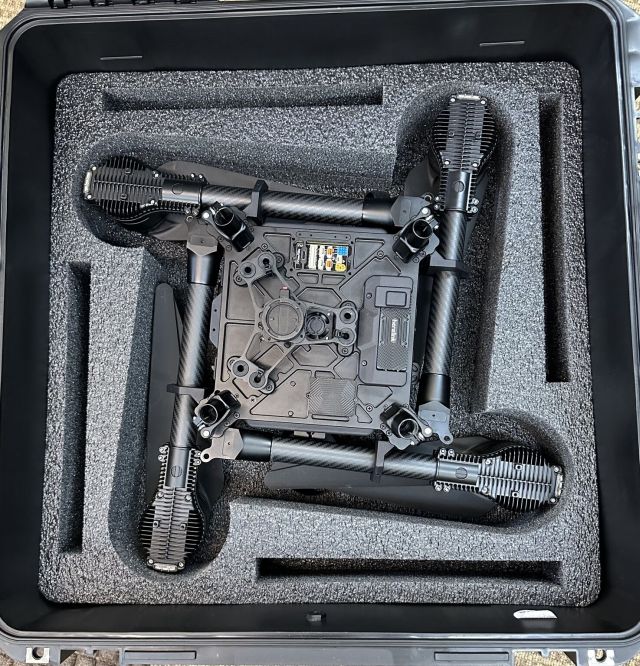

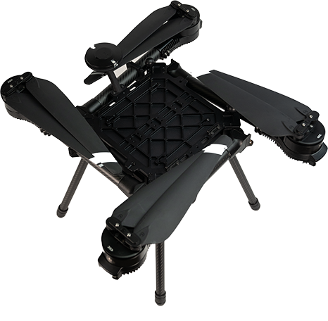


.avif?alt=media&token=14627f02-25ba-4287-9e6c-7141c7d7812d)
.avif?alt=media&token=92708228-12b2-410f-b4ed-c8261a6c21bb)
.avif?alt=media&token=004bc305-16cd-4f38-bd66-165cc91b9170)


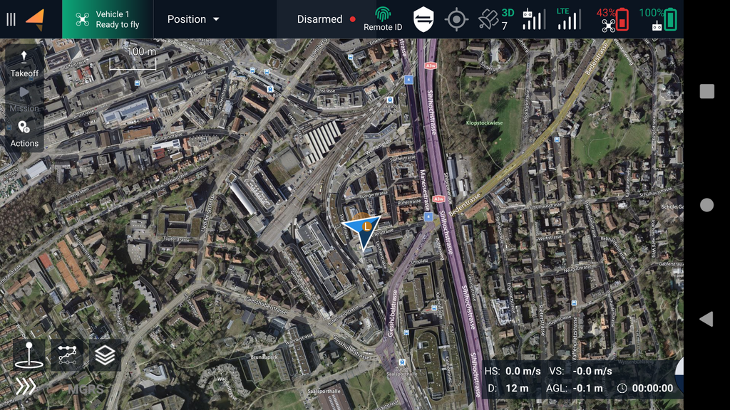


.jpg?alt=media&token=300fdbde-7a6f-44fb-9317-e10095e7c530)


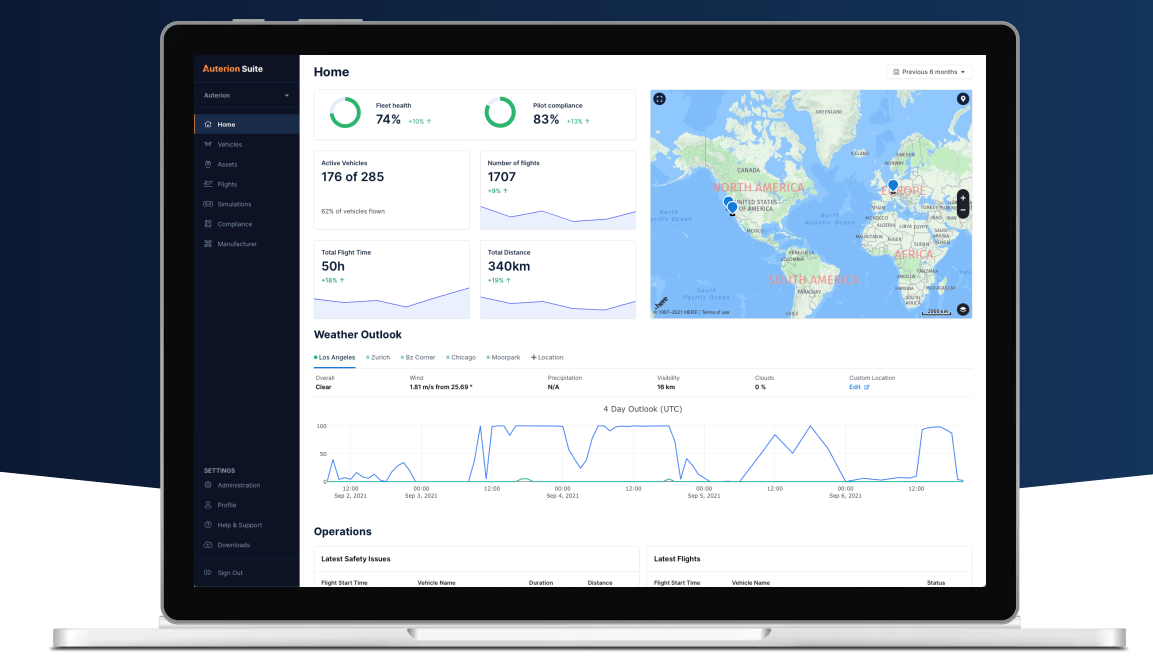


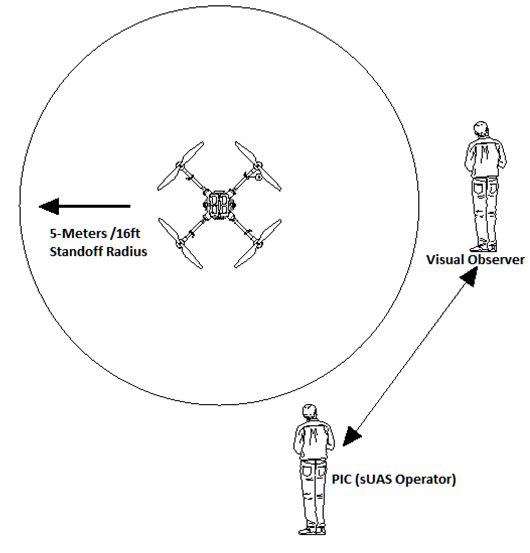
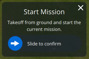


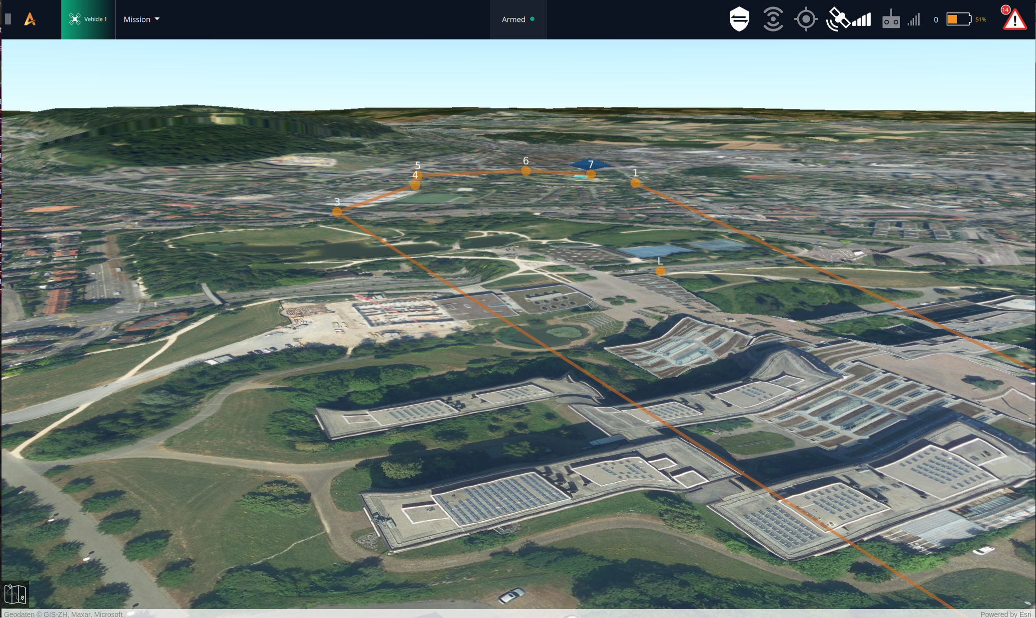
.png?alt=media&token=e7d01c57-e7f2-4cd4-a006-bcba47375cf0)
.png?alt=media&token=525839c4-4207-4a95-9545-8df5fe52760e)
.png?alt=media&token=05bcd121-fbb6-4d14-9b0e-264475b06d2a)
.png?alt=media&token=e47d11d0-b0f3-4f06-86c0-85f237917764)
.png?alt=media&token=1339c3df-8782-4435-b55f-7fd31cbfe910)




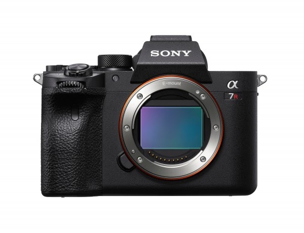
 2. Navigate to the *Network1* tab and open *PC Remote Function*.\
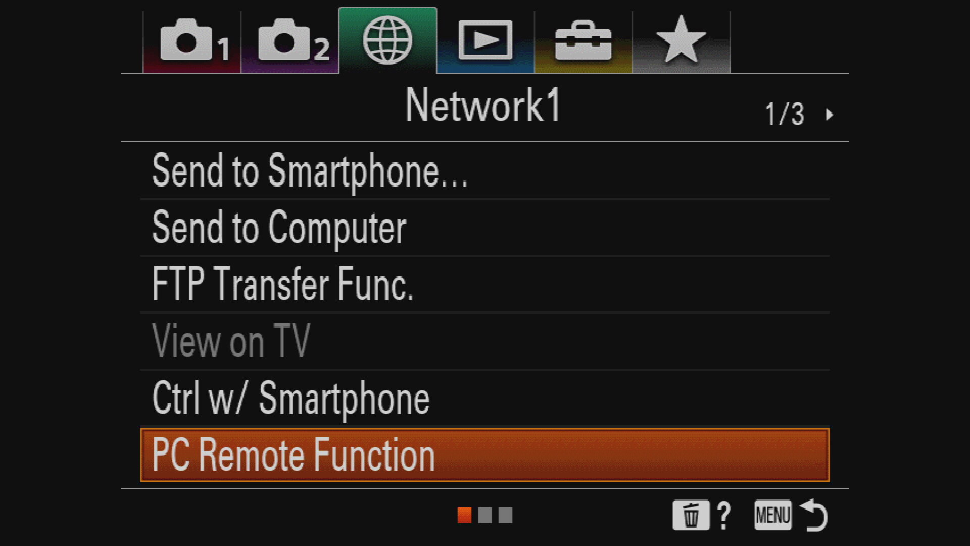 3. Set *PC Remote* to **On** and make sure *PC Remote Cnct Method* is set to **USB.** \
 4. Exit the dialog by pressing the **MENU** button.
Still under "Controls", select "Mavlink", this time select YES when prompted to enable MAVLink input
4. Exit the dialog by pressing the **MENU** button.
Still under "Controls", select "Mavlink", this time select YES when prompted to enable MAVLink input


.png?alt=media&token=07a61353-b5b4-49cf-9eba-e17a7e508ef1)


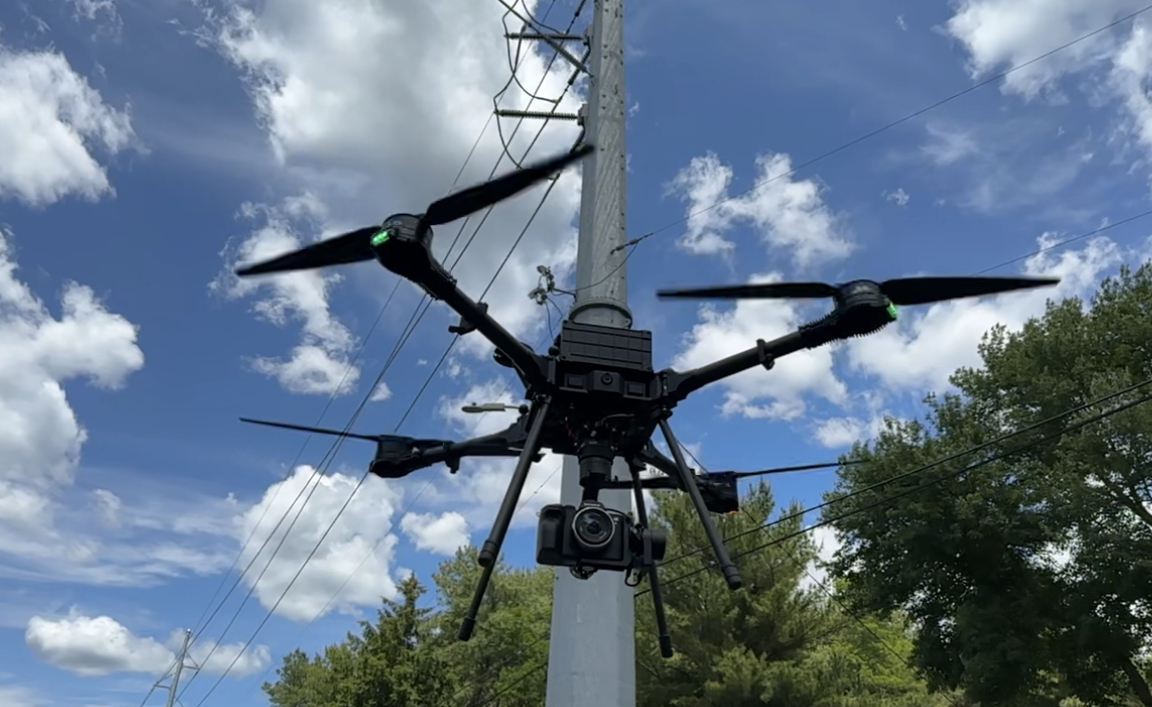
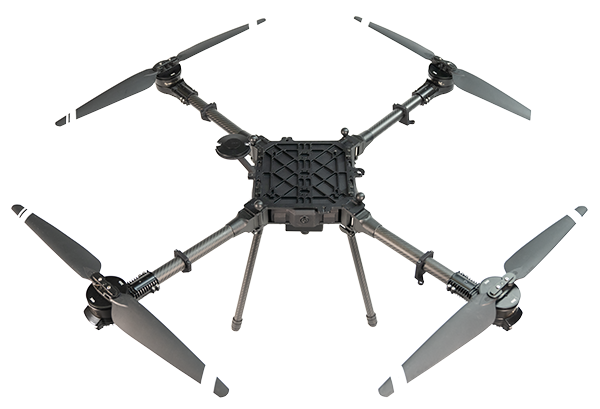
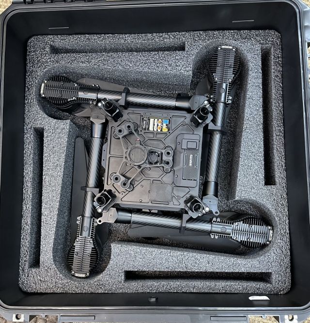
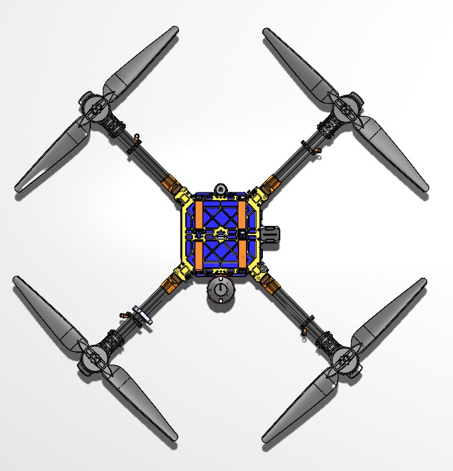
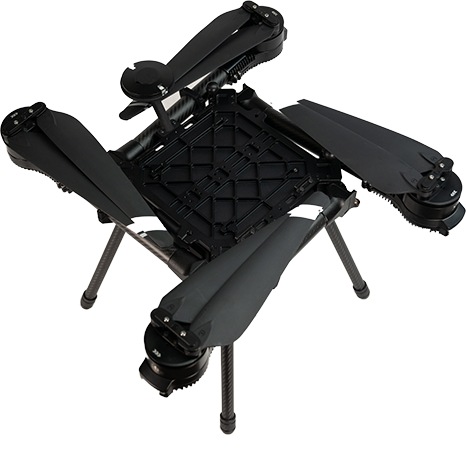
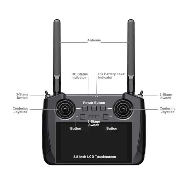
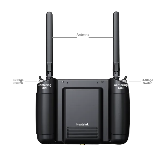
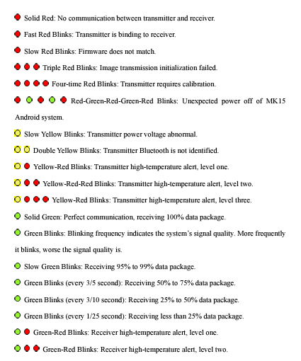
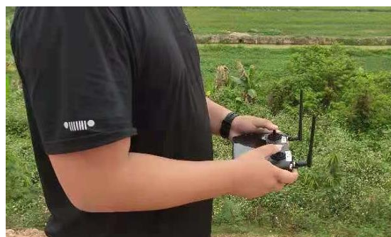
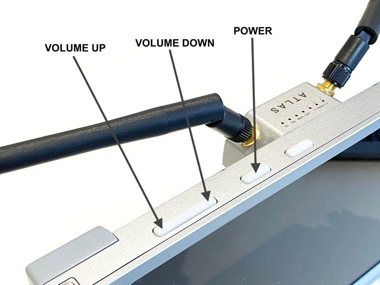
.avif)
.avif)
.avif)