> For the complete documentation index, see [llms.txt](https://docs.camflite.com/llms.txt). Markdown versions of documentation pages are available by appending `.md` to page URLs; this page is available as [Markdown](https://docs.camflite.com/crd1/payload/i-o-board-and-payload-power.md).
# I/O Board and Payload Power
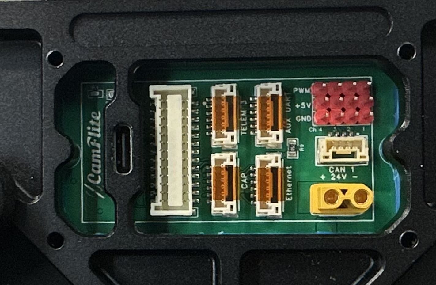
The Input/Output (I/O) board, which is located at the bottom, acts as an interface between the Flight Management Unit (FMU) and various other components. It enables the FMU to access and control the rangefinder, nadir camera, and other similar devices, allowing for more efficient and accurate operation.
Onboard Power
The I/O board has a 24V power output for payloads on a Molex connector. It comes from a fused switching power supply that steps the battery voltage down to a regulated 24V. The white plug carries 12S battery power.
Separate from the I/O board, there's an XT60 plug on the bottom of the drone that's only for powering CRD1. You can plug in a 12S LiPo or a 48V wall power supply there, which is handy for updates and downloading logs on the bench.
The I/O board has LEDs that light up when the power supplies are working. If any of them isn't lit, contact Camflite.
## I/O outputs
USB-C for webcam, flash storage, etc
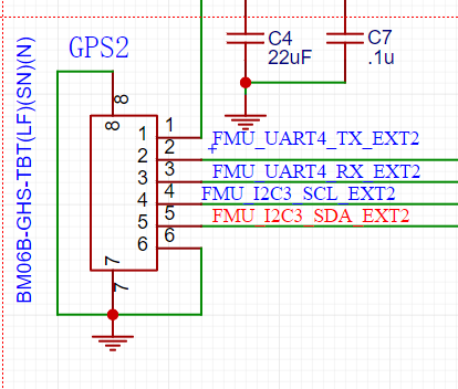
**Telem1**- UART4 and I2C from FMU
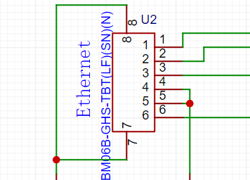
**Ethernet**- for camera or other network-based payloads
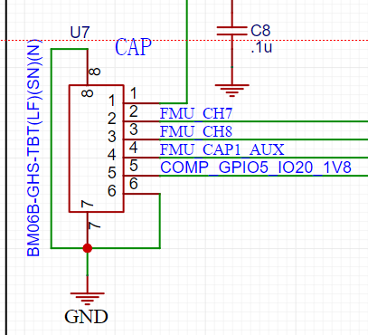
**Cap**- FMU CH 7 and CH 8, FMU CAP, and one GPIO from MC
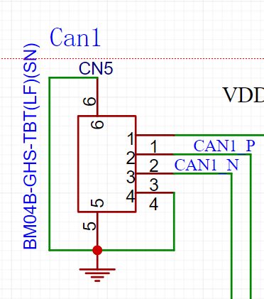
**Can1**- CAN from FMU
**PWM**- ch7-8
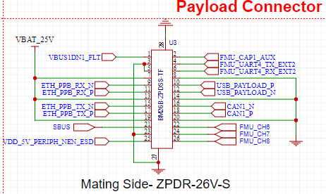
## Payload Connector
Payload Pinouts
## USB-C FMU Plug
The Aurora drone features an exclusive USB port that is situated at the bottom of the device. This USB port is dedicated to direct connection to the onboard mission computer, which manages and coordinates the drone's operation. With this USB port, you can comfortably perform essential tasks such as upgrading the drone's firmware and communicating with the Flight Management Unit (FMU).To establish a connection with the flight computer, it is essential to power up the Aurora device as the USB port alone does not provide any power. Thus, you will need to ensure that the Aurora device is powered on before attempting to communicate with the flight computer.